Don't forget to update your personal camera inventory
CollectiBlend
Antique and classic cameras/lenses price guide.PHOTOGRAPHIC LENSES
by C.B. Neblette.(c) 1952
Excerpt from the "Photography Its Materials And Processes" book (public domain according to the archive.org)
The basic requirement of a camera lens is that it form an image of an object with acceptable definition over a specified field angle. Where the requirements of performance are not very strict, this can be accomplished quite simply with a single lens element. The stricter the requirements the more complex the lens must be.
The Meniscus Lens. The simplest camera lens is the meniscus, which is normally found in inexpensive box cameras. In the design of the single lens the designer has only two degrees of freedom - the shape of the lens and the position of the diaphragm. These two degrees of freedom permit him to control only two of the seven basic aberrations. Obviously, with only one element he cannot control either of the color aberrations. Of the five monochromatic aberrations which remain, the two most readily controlled are astigmatism and coma. Inasmuch as the lens must be used at small relative apertures, we are justified in leaving the spherical aberration uncontrolled. The field curvature (often called Petzval Sum after Josef Petzval who developed the concept by which field curvature is calculated) can be controlled to a minor degree through the selection of glass, but this degree of freedom has only a minor effect and for most practical cases is not used. Normally the criterion governing the choice of glass is cost, which dictates that the least expensive glass be used inasmuch as the lens is in tended for an inexpensive camera. Distortion and astigmatism cannot be con trolled simultaneously, and, of the two, astigmatism is the more important since it affects definition and field coverage, whereas distortion is an aberration of position.
In the design of a simple lens, the lens shape is used to control the astigmatism. The word control is used because, in the presence of field curvature, astigmatism cannot be fully corrected on a flat image plane. Coma can be well corrected by the proper positioning of the diaphragm.
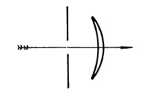
FIG. 5.1. Single lens.
The meniscus lens (Fig. 5.1) may be placed behind or in front of the diaphragm. The two positions have their advantages and disadvantages and the choice depends upon the application. The front meniscus permits making a shorter camera box since the total camera depth need not exceed the focal length of the lens. In the case of the rear meniscus, however, we must add to the focal length the distance to the stop to find the required camera depth. Another disadvantage of the rear meniscus lies in the mere fact that the stop is out front and should be protected by a cover glass to keep dust and dirt out of the camera and the shutter mechanism, which is usually located next to the stop.
The front meniscus is characterized by positive or pincushion distortion, while the rear meniscus exhibits negative or barrel distortion. If you must have distortion, barrel distortion is usually considered less objectionable because it tends to make the corners of a picture appear tied down, whereas pincushion distortion gives the impression that a picture is flying apart at the corners. In this respect the rear meniscus could be considered to have the advantage.
In the front meniscus both the tangential and radial foci can be made to fall close to the curved field surface of the lens, thus producing very little astigmatism over rather large field angles. If the film plane of the camera can be curved to fit this focal surface, surprisingly good results are obtainable at apertures of about f/16. With the rear meniscus the best compromise obtainable places the tangential field on a flat plane with the sagittal focus inward curving (toward the lens). The camera in this case is designed to hold the film flat, and the off-axis definition is not as good as on the curved field of the front meniscus.
Symmetrical Lenses. A symmetrical lens is symmetrical about the diaphragm. In other words, that part of the lens be hind the stop is a mirror image of the part ahead of the stop. The advantage of a symmetrical lens lies in the fact that the lateral aberrations - i.e., coma, distortion, and lateral color - of each half of the lens will be of opposite sign and will balance each other. This is strictly true only in the case where object and image are equidistant from the stop, and the magnification is therefore unity. However, even with a considerable departure from unit magnification, there is still a partial balance of the lateral aberrations in a symmetrical lens.
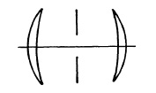
FIG. 5.2. Symmetrical lens.
Let us take half the power away from a front meniscus landscape lens and place a second element symmetrical to the front element behind the stop, as shown in Fig. 5.2. Now the positive distortion introduced by the front is compensated by the negative distortion contributed by the rear element. The same principle applies to the lateral color and to coma. In the case of the single meniscus lens the stop was positioned to correct coma, but this is no longer necessary since symmetry takes care of that problem, and we may now use the stop position, and consequently the lens separation, to control the field curvature to some extent.
At large field angles the lateral aberrations become the designer's most serious problems. Thus most wide-angle lenses are symmetrical types, with the exception of cases where positioning limitations require the use of reversed telephoto designs. The other common use of symmetrical lenses is in copy work and other applications where the magnification does not vary greatly from unity.
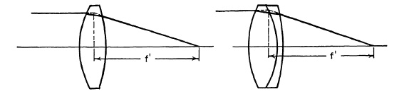
FIG. 5.3. Simple lens and achromat of the same focal length.
The Achromat. A simple symmetrical lens, as shown in Fig. 5.2, provides no means of correcting for longitudinal color. As was mentioned in the discussion of longitudinal color, it is corrected by the proper use of two elements of the opposite power and having different dispersions. The process is not quite so simple as this, however, and has some drawbacks. In order to achromatize a lens and maintain its focal length it is necessary to strengthen the positive element considerably to compensate for the negative power which is introduced to correct the color aberration. If the lens is to have net positive power, the positive element must have more power than the negative element. The color correction is accomplished by selecting a glass of low dispersion for the positive element. This, in combination with a weaker negative element of high dispersion, will provide a net positive power. The relative powers of the two elements can be computed to bring any two selected wave lengths of light to a common focus. If common crown glass is used in the positive element and common flint glass in the negative element, each will be stronger than the simple positive lens of the same net power. The crown glass element will have about 2½ times the net power of the system, and the flint glass element will have about 1½ times the net power.
It is apparent from Fig. 5.3 that considerable bulk is added to a lens when it is achromatized. The achromatic doublet has only three degrees of freedom, assuming the stop is in contact with the lens. They are the ratio of powers of the two elements, used to correct color; the bending of the whole lens, used to correct spherical aberration; and the choice of index of refraction of the glasses, which, when combined with bending, permits simultaneous correction of coma and spherical aberration. Field curvature and astigmatism are not controlled. Consequently, the lens has a limited field of view of only a few degrees. The achromatic doublet is used little in photography, but is commonly used as a telescope objective. Photographic applications are limited to lenses of extremely long focal length covering small field angles. For this purpose relative apertures as great as f/5 have been obtained.
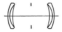
FIG. 5.4. Rapid Reetlinear (Dallmeyer) and Aplanat (Steinheil).
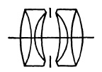
Symmetrical lenses composed of two achromatic doublets separated by the diaphragm, however, have an important place in photographic history. The first successful lenses of this type (Fig. 5.4) were brought out in 1866 independently by Steinheil of Munich as the Aplanat and by Dallmeyer of London as the Rapid Rectlinear. The first lenses had an aperture of f/8 and a field of about 50°. Later lenses of larger aperture, but smaller field coverage, were placed on the market primarily for group and full-figure photography. The aplanat and rapid rectlinear, under a variety of trade names, continued in general use on amateur hand cameras until well into the twentieth century.
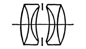
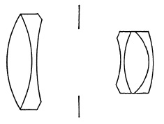
Symmetrical Anastigmats. The first anastigmat lenses to find wide acceptance among photographers were of the symmetrical type with either three- or four-glass cemented elements (Fig. 5.5). The best known of the three-glass lenses is the Goerz Dagor (1892), although similar lenses with different arrangements of the cemented lenses were placed on the market by Steinheil as the Orthostigmat, and by Voigtlander as the Kollinear.
(a) Goerz Dagor f/6.8.
(b) Zeiss Protar f/6.8.
FIG. 5.5. Double anastigmats.
The Protar (1893) of Carl Zeiss is the best known of the four-glass lenses. Similar lenses have been made by many other manufacturers with only minor changes as, for example, the Raptar Ia f/6.8 of Wollensak. In the Convertible of Taylor, Taylor and Hobson, an air space separates the four glasses into two cemented pairs (Fig. 5.6). A number of five-glass lenses have been made, the best known being the Turner-Reich Anastigmat of Gundlach.
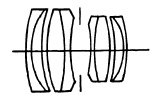
FIG. 5.6. Taylor, Taylor and Hobson Convertible.
These lenses have a maximum aperture of f/6.8 and include an angular field of from 60° to 70°, depending upon the aperture, the useful field increasing with smaller apertures. The front and rear portions may be used separately for the longer focal length. Thus, if the focal length of the front and rear portions are different, three focal lengths are available. The maximum useful aperture of the single lenses is about f/12.5. The convertibility, the large flat field and brilliant image, make these lenses popular with commercial photographers, although no new lenses of these types have been de signed for several years.
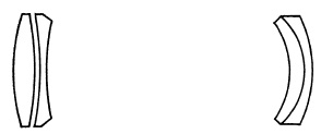
Wide-angle lenses of this type (Fig. 5.7) include an angle of from 80° to 90° and have a maximum aperture of f/6.8 to f/9.5, but it is usually necessary to stop down to about f/16 if the full field of the lens is used.
(a) Schneider Angulon f/6.8.
(b) Goerz Dagor f/6.8.
(c) Wollensak Wide-Angle Eaptar f/9.5.
FIG. 5.7. Double anastigmats (wide angle).
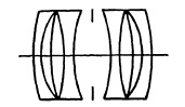
A number of useful designs have been developed from these by adding air spaces. The design shown in Fig. 5.8, produced by reducing the power of the central lens to zero, does not include a wide field but is noteworthy for the uniformity in its per formance over a wide range of image-to-object ratios. It has been used in recent years primarily for process lenses.
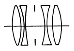
FIG. 5.8. Four-element, symmetrical type lenses: Goerz Artar f/9.5; Goerz Gotar f/8; Kodak Ektar f/7.7.
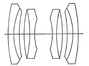
Another development in which the inner lens has been separated from the other two by an air space is shown in Fig. 5.9. The additional constructional elements available to the designer make apertures up to f/4 possible with an angular field only slightly smaller than that of the cemented element.
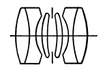
FIG. 5.9. Six-element, symmetrical type lenses. Meyer Double Plasmat; Schneider Symmar
The Triplet. The simplest lens that can be designed containing sufficient degrees of freedom to correct all seven basic aber rations is the "Cooke" triplet, first designed by H. Dennis Taylor in 1893. This lens, illustrated in Fig. 5.10, has just seven degrees of freedom, three powers, three glass choices, and the ratio of the two air spaces (1). As one might surmise, there are innumerable solutions to this design problem depending upon the parameters selected by the designer, or fixed by physical location requirements for the elements. The triplet is probably the most common photographic objective in use today, with the exception of the meniscus lens of the box camera. With the use of new high-index glasses, triplets have been designed with relative apertures as great as f/1.9 for short focal length applications, such as 8mm. movie photography. In 35mm. photography, triplets of f/2.8 and f/3.5 apertures are very common, while for larger negative sizes f/4.5 has been a practical limit of relative aperture for triplets. The triplet can be readily designed to cover a full field of view equal to its focal length with adequate image quality and is, therefore, a very common "normal" focal length lens of moderate aperture for still photography.
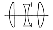
FIG. 5.10. The simple triplet.
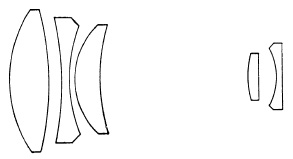
Developments of the Triplet. Lens designers, from time to time, have increased the number of elements of the triplet to obtain greater freedom in making the necessary corrections for (1) a larger aperture, (2) a larger field, (3) improved correction, or (4) all three of these. The first development historically was made by Harting, who calculated for Voigtlander a triplet in which the outer single lenses became cemented doublets (Fig. 5.11). This was brought out as the Heliar f/4.5 and has been popular as a portrait lens. The aperture was extended to f/2.9 by L. B. Booth in a lens introduced in 1920 by Dallmeyer of London as the Pentac.
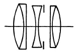
FIG. 5.11. Triplet lens with compound exterior elements. Voigtlander Heliar f/4.5; Voigtlander Lanthar f/4.5 ; Kodak Ektar f/3.7.
In the Aviar, f/4.5, of Taylor, Taylor and Hobson (Fig. 5.12), the central negative lens of the simple triplet is divided into two of lower power to improve the correction for coma. In the Tachar of Astro, one of the outer positive lenses has been divided into two of lower power. In the Hektor f/6.3 of Leitz, the central negative lens has been made into a doublet; and in the Hektor f/2, all three elements are cemented doublets. These two lenses are no longer made.
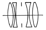
FIG. 5.12. The Aviar of Taylor, Taylor and Hobson.
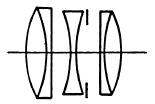
The Tessar (Fig. 5.13), designed by Paul Rudolph for Carl Zeiss (1903), was not actually derived from the triplet but may be regarded as a triplet in which one of the outer elements has been made into a cemented element of two lenses. This is one of the most popular lenses ever designed. Originally it had an aperture of f/4.5, but with the newer glasses now available it is made up to f/2.8. Its performance is superior to the triplet particularly in the reduction of astigmatism which improves the imagery at the margins of the field or may permit a larger angular field. In some cases (Ross XPres and Gundlach Radar), it has been made with a rear element of three cemented lenses. (2)
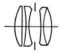
FIG. 5.13. The Tessar of Zeiss.
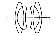
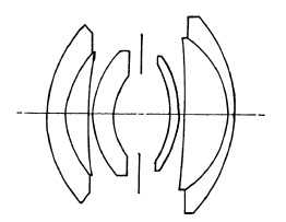
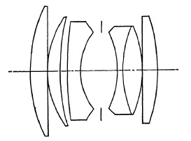
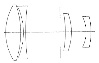
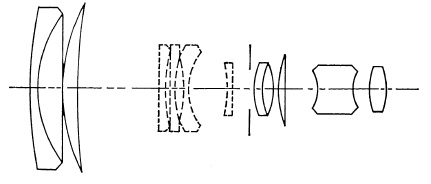
The Sonnars (Fig. 5.14) of Zeiss represent a development of the Tessar design for apertures of f/2 and f/1.5 for use on 35mm. cameras. Intrinsically, this design is not as suitable for large aperture lenses as the Gaussian construction; there are, however, many excellent lenses of this type for the 35mm. camera.
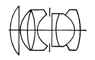
FIG. 5.14. The Zeiss Sonnar f/1.5.
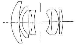
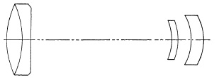
The long-focus Sonnars (Fig. 5.15) have also been widely copied either directly or in modified form. Most of these are for the 35mm. camera but some are suitable for the 60 X 60mm. (2¼x2¼) format.
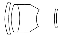
FIG. 5.15. The Zeiss Sonnar (longer focal lengths).
Gauss-Type Lenses. The German mathematician, K. F. Gauss, in his studies on the design of the astronomical telescope, found that the variation in spherical aber ration with wave length could be eliminated by using meniscus-shaped crown and flint glass elements separated by an air space functioning as a negative lens. A symmetrical photographic lens of this type (Fig. 5.16) was designed by Kollmorgen in 1900 and introduced commercially by Hugo Meyer as the Aristostigmat. This, and other lenses of this design, are excellent commercial and wide-field lenses at moderate apertures (f/6.3 to f/6.8). The wide-angle lenses of this construction require much smaller apertures if the full angular field of the lens is used.
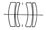
FIG. 5.16. The four-element (1) wide angle and (2) process lens: Dallmeyer Wide Angle; Kodak wide field Ektar; Ross Homocentric Process f/10; Kodak Process lens f/10; Wollensak Raptar Process f/10. This design is also widely used for process lenses.
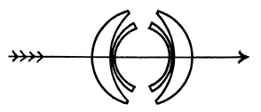
FIG. 5.17. The Zeiss Topogon; Wide-angle, large-aperture lens for aerial photography.
(a) Canon 28mm. f/2.8.
(b) Nikkor 25rnm. f/4.
FIG. 5.18.
This design, introduced originally by Zeiss as the Topogon (Fig. 5.17) and by Bausch and Lomb as the Metrogon, was later developed for aerial mapping with an aperture of f/6.3 and low distortion over a field of 100°. A number of similar lenses have been made as wide-angle lenses for the 35mm. camera (Fig. 5.18).
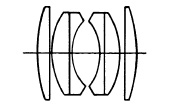
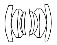
FIG. 5.19. The Zeiss Planar.
In 1893, Rudolph, starting with the Gauss objective, designed a lens in which the two inner lenses were cemented doublets (Fig. 5.19). This was produced by Zeiss as the Planar with an aperture of f/3.5. As a symmetrical lens, the design could not be corrected well for coma except over a relatively small field. The Tessar, introduced in 1903, replaced it for general photography but the Planar is still made as a process lens (3).
(a) Kern Switar f/1.8.
(b) Minolta Rokkor f/2.
(c) Voigtlander Septon f/2.
(d) Leitz Summicron f/2.
(e) Fujinon f/1.2.
(f) Leitz Summarit f/1.5.
FIG. 5.20. Developments of the Planar design.
In 1920, Lee of the firm of Taylor, Taylor and Hobson returned to this design and found that the correction for coma could be greatly improved by departing from a strictly symmetrical construction. The design, as developed by Lee, was found to be especially favorable for the correction of spherical aberration and notable for the uniform distribution of all the aberrations over the entire field with less variation from center to edge than other designs at the same aperture. The Opic, with an aperture of f/2 and a well corrected field of 48°, called the attention of other designers to the potentialities of this design for large aperture lenses. With the increasing demand for large aperture lenses, this so-called Gaussian or Planar design has become one of the most important in the field of photographic optics. Important developments are being made almost constantly. Some of these are shown in Fig. 5.20.
(a) The Zeiss Biogon.
(b) The Schneider Super-Angulon.
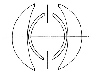
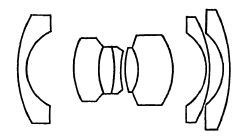
The Biogon of Zeiss and the Super-Angulon of Schneider and Leitz represent further developments of the Gauss design for extreme wide-angle lenses (Fig. 5.21). The 21mm. f/4.5 Biogon and Super-Angulon include an angle of 90° on 24x36 mm. The Super-Angulon f/8 for the larger camera is made up to 210mm. focal length and includes an angular field of 90°. The definition is excellent at full aperture.
A simplified Gauss design, shown in Fig. 5.22, has been very successful for the larger camera at apertures up to f/2.
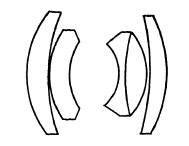
FIG. 5.22. The Zeiss Planar f/2.8 (new type), Schneider Xenotar f/2.8, Wray Unilite f/2.0.
Long-Focus Lenses. Long focal length lenses for all except the large stand cameras are usually of the telephoto type; otherwise the lens becomes too long and heavy, making the camera difficult to use. An alternative is to mount the lens on a tripod and attach the camera to it. If this is done, complex telephoto designs can be replaced with much simpler combinations of lenses. Since the angular field is small, modified astronomical objectives (Fig, 5.23) may be used in focal lengths of 300 to 1000 mm. on 35mm. cameras and, in the longer of the focal lengths, for 2¼x3¼ cameras. Long-focus lenses of this and similar types are almost an exclusive product of several European manufacturers, notably Astro, Meyer, Tewe, and Killfit.
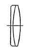
FIG. 5.23. Long-focus lenses (Fernbildlinse).
Lenses with Interchangeable Front Components. To provide lens interchangeability on cameras with lens shutters, several manufacturers have designed lenses in which the front portion only is removed and another substituted to obtain a different focal length. The lens system is rather complicated (Fig. 5.24) and, although generally satisfactory, the performance of lenses of the type does not equal that of lenses which are interchanged as a unit.
1. The Protessar of Zeiss (a) wide field; (b) long focus.
2. The Curtagon of Schneider (a) wide field; (b) long focus.
FIG. 5.24. Front-component interchangeable lens systems.
Telephoto Lenses. The first telephoto lenses were designed by Steinheil of Munich, and Dallmeyer of London, late in the nineteenth century. They were negative lens attachments for use behind conventional lenses and were mounted in tubes so that the focal length of the complete lens system could be changed to regulate the size of the image. These were unsatisfactory for general use because of excessive curvature of field and astigmatism, as well as the small aperture. Several years later it was realized that better correction and a larger aperture would be possible if the lens was designed as a whole.
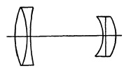
FIG. 5.25. Early fixed magnification telephoto lens. The Sis-Telar of Busch.
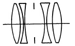
The first fixed-magnification telephoto lens appears to have been the Bis-Telar (Fig. 5.25) of Emil Busch (Rathenow) which was placed on the market in 1906. Similar lenses were brought out by Zeiss (the Magnar f/10), Dallmeyer (Adon f/4.5), Ross, and other opticians. These suffered severely, however, from astigmatism, curvature of field, and distortion.
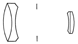
FIG. 5.26. The Dallmeyer Dallon telephoto lens.
In 1914, Booth designed a telephoto lens for Dallmeyer with an aperture of f/6 in which the corrections for astigmatism, curvature of field, spherical and chromatic aberration were greatly improved over the earlier lenses. This lens was redesigned and improved in 1920 and placed on the market as the Dallon with an aperture of f/5.6 (Fig. 5.26). This was the first well-corrected telephoto lens and as such was widely copied by others.
(a) Ross Teleros.
(b) Zeiss Teletessar.
FIG. 5.27.
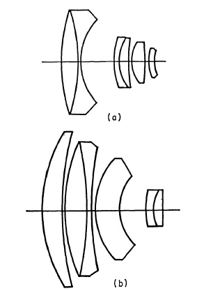
At first the changes were minor (Fig. 5.27); however, as time went on and the demand for larger aperture lenses increased, particularly for the 35mm. camera, designers began to experiment with other constructions. A number of these are shown in Fig. 5.28.
(a) Steinheil Tele-Quinon 135mm. f/3.5.
(b) Leitz Telyt 200mm. f/4.
(c) Rokkor 135mm. f/4.
(d) Canon 200mm. f/3.5.
(e) Topcor 200mm. f/2.8.
(f) Teletessar 500mm. f/8.
FIG. 5.28. Several telephoto lenses for the 35mm. camera.
The telephoto lens is being constantly improved, particularly for the 24x36 negative. It does not equal in performance good-quality conventional-type lenses of the same focal length, but the difference is for most purposes insignificant and the reduced weight and length make it more convenient in use.
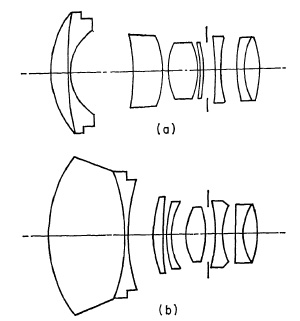
Inverted Telephoto Lenses. The inverted, or reversed, telephoto construction (see Chapter 4) is used chiefly for wide-angle lenses for single-lens reflex cameras and cameras in which the lens is mounted in front of a lens shutter. Typical commercial examples are shown in Fig. 5.29.
(a) Angenieux, Retrofocus 24mm. f/3.5.
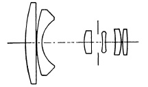
(b) Nikkor 28mm. f/3.5.
(c) Schneider Curtar 35mm. f/2.8.
(d) Steinheil Quinon f/1.9.
FIG. 5.29. Several inverted telephoto lenses.
Reflecting Systems. Among the variety of special-purpose optical systems in use in photography today, reflecting systems are assuming an increasingly important role. When requirements for relative aperture exceed f/I, refracting optics become exceedingly complex and expensive; but, if the field coverage need not be large, reflecting optics of remarkable simplicity can provide excellent definition. Examples of this are the Schmidt system (Fig. 5.30) consisting of a single spherical mirror with an aspheric corrector plate at its center of curvature. The focal length of a spherical mirror is one half its radius of curvature, and it has a field curvature with a radius also equal to one half the mirror radius. The corrector is the aperture stop of the system. Its surface corrects the spherical aberration, whereas its position is used to correct coma. If a curved field can be used, excellent definition can be obtained over 8° to 10° of semifield at apertures of f/I or greater. Because of their great light-gathering capacity, Schmidt systems are in common use in astronomical cameras. Schmidt systems have also found valuable use in television projectors, where the curved tube face fits very nearly the field curvature of the mirror and the large relative aperture is required to provide the highest possible screen brightness of the projected picture.
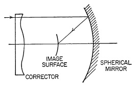
FIG. 5.30. Schmidt System.
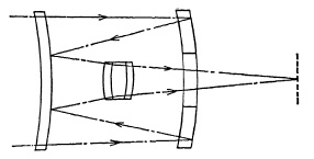
An interesting modification of the Schmidt system employs a meniscus corrector lens having spherical surfaces to replace the aspheric corrector. The meniscus corrector is positioned near the image surface, and the two surfaces of the corrector are nearly concentric with the mirror surface, as shown in Fig. 5.31. The reflector system with meniscus corrector is well corrected for spherical aberration up to a relative aperture of f/I, but for larger apertures the aspheric Schmidt-type corrector is essential for adequate spherical aberration correction.
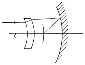
FIG. 5.31. Reflector with meniscus corrector.
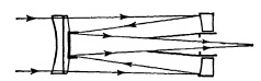
Such systems as these, containing both refracting and reflecting optics, are called catadioptric. This category probably en compasses most so-called reflecting systems. However, there are some designs of entirely reflecting systems, as illustrated in Fig. 5.32. Such a system, by folding the beam and reversing its direction twice, provides an extreme telephoto effect, such that the system length from the front vertex to the image can readily be made one third of the focal length or less.
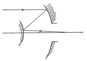
FIG. 5.32. Reflecting lens systems.
One advantage of an optical system consisting entirely of reflecting surfaces is the complete absence of chromatic aberrations, a very desirable condition when a system must be used over a very broad spectral region.
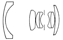
The Mirrotel of Wollensak (Fig. 5.33a) is made in focal lengths of 40 and 80 in. (100-200 cm.) with maximum apertures of f/B and f/14, respectively. The Reflex-Nikkor, with a focal length of 1000mm. and an aperture of f/6.3, is similar. The Reflectar of Zoomar Inc. (Fig. 5.33b) is made in several focal lengths with an aperture of f/5.6. The front and rear lenses and mirrors constitute the positive component of the telephoto system; the inner lenses, the negative component.
(a) The Mirrotel of Wollensak.
(b) The Eeflectar of Zoomar.
FIG. 5.33.
Aspheric Surfaces. As the relative aperture of a lens is increased (f/number reduced) it becomes increasingly difficult to correct the spherical aberration to reasonable quality at all zones of the aperture. Consequently, high aperture lenses become very complex in order to provide satisfactory correction at full aperture, and still give good performance when stopped down. In such cases it may be possible to develop a simpler design employing an aspheric surface which is calculated specifically to compensate the spherical aberration at all zones of the aperture of the lens system. By aspheric, we mean here a nonspherical surface of revolution about an axis which is normally the optical axis. (Cylinders and toroids are aspheres in the broad sense of the word, but are excluded by the above definition. In terms of application to optical systems, they form a separate class of surface.) The Schmidt system discussed previously is an excellent example of the use of an aspheric surface to provide complete spherical aberration correction of the simplest possible optical system, the spherical mirror.
Polished aspheric surfaces are very costly to manufacture to the close tolerances required for photographic optics. Their use so far has been limited to lenses where cost has been no object or where there is no other feasible solution to a problem. Molded aspheric surfaces are often used in condensers and view finders where the surface quality need not be nearly as good as that required of a photographic objective.
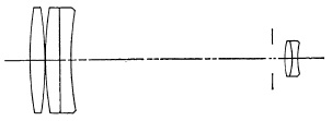
Afocal Supplementary Lenses. In addition to the simple attachment lenses designed to accommodate different object distances, there is a class of lens attachments designed to change the focal length of a camera lens without changing the image distance or back focus. Such attachments, commonly called converters, are actually Galilean telescopes. A telescope is afocal; i.e., its focal length is infinite. Therefore a beam of light from a distant object, after passing through a telescope, will still appear to come from the same distance, but the beam will be larger or smaller in diameter, depending upon the magnifying power of the telescope. The magnifying power of a telescope is equal to the ratio of the focal lengths of the objective and eyepiece, or m = fo/fe, which is equal to the ratio of the beam diameter at the objective to that at eyepiece.
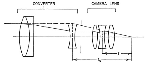
FIG. 5.34. Telephoto converter lens system.
Fig. 5.34 illustrates the principle of a converter designed to increase the focal length of a camera lens. The ratio of the combined focal length of the camera lens plus converter (fc) to that of the camera lens alone (f) is equal to the magnification of the converter. By reversing the Galilean telescope converter, so that its magnification is less than one, the focal length can be decreased, as shown in Fig. 5.35. Note that with either converter the back focus of the camera lens is unchanged. Also the relative aperture of the combination is the same as the camera lens alone. As a result of the change in focal length produced by the addition of a converter to a camera lens, the focus of the combination for near objects will be changed. This must be accounted for on a focusing lens by changing the distance scale, and on a fixed-focus lens by a revision of the depth of field limits. Wide-angle and telephoto converters of this type are used on amateur movie cameras to provide the versatility of a multiple-lens camera at reasonable cost to the camera owner.
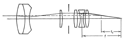
FIG. 5.35. Wide angle converter lens system.
Zoom Lenses. The name "Zoom" lens has been applied to any lens with a variable focal length. Zoom lenses were first used on television cameras and have gradually progressed into professional and amateur movie fields. The variation in focal length in a zoom lens is accomplished by moving one or more lens components longitudinally in the system. The zoom range is the ratio of maximum to minimum focal length.
A logical classification of zoom lenses may be made in terms of the number of components the zoom system contains up to and including the last movable component. Lens elements to the rear of the last moving element constitute the fixed portion of the lens and serve to place the image in the desired plane at the desired size. They also have a constant effect on aberrations regardless of the zoom, or focal-length, setting of the movable portion.
A zoom system must have at least two components to provide a variation in focal length. A two-component zoom lens can be designed to have a common image plane for only two focal lengths within its zoom range. At these two settings the focus is said to be compensated, and at all other focal-length settings the image will deviate from this image plane. The curve of focus as a function of focal length is a second-order curve, and the excursion from the desired image plane is normally too large to be acceptable without refocusing the lens. Therefore, in two-component systems a third element is usually added, moving differentially with the zoom component to maintain focus throughout the zoom range. Such a system is illustrated in Fig. 5.37. The third element in this case should not be considered part of the zoom system since its motion is not employed to vary the focal length of the lens.
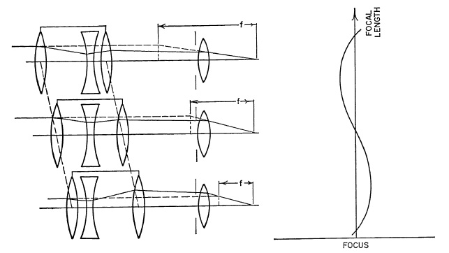
FIG. 5.36. Three-component zoom lens systems.
As the number of components in the zoom portion of a lens is increased, the number of compensated focal lengths is increased. A three-component zoom lens can have three focal lengths at which the focus is compensated. A four-component system can have four compensated focal lengths, and so on. If properly designed, the focus excursions between the points of compensation of zoom systems of three and more components can be kept within the depth of focus of the lens, thus requiring no differential motion as required in the two-component system. A typical three-component zoom lens configuration is shown schematically in Fig. 5.36. Note that the first and third components move as a unit.
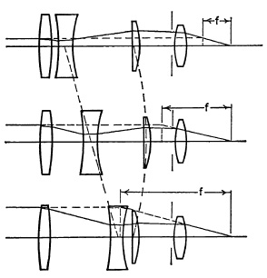
FIG. 5.37. Two-component zoom lens systems.
The practical limit of zoom range obtainable is roughly equal to the number of components in the zoom portion of the lens, but it is dependent upon many variables. This limitation results from the fact that the excursions of focus between compensated focal lengths increase with the zoom range for a given number of components. If the relative aperture of the lens is small, resulting in a large depth of focus, or if focus compensation is not critical, or is accomplished by some differential motion, as in Fig. 5.37, the zoom range limitation may be increased considerably. Also the focus excursions decrease rapidly with increasing numbers of components, and the corresponding increase of compensated points, for a given zoom range. Pour-component systems with zoom ranges up to 6:1 have been developed.
A further practical limitation appears to be the number of components in a zoom lens. As the number exceeds four, the lens becomes excessively large for most practical uses. Consequently, very few zoom lenses have been designed with more than four components.
In any zoom lens it is necessary to place the diaphragm behind the last moving element if the relative aperture is to remain constant throughout the zoom. If for any reason the diaphragm must be located ahead of the last movable element, where the beam diameter varies with zoom, some mechanical arrangement is necessary to vary the aperture size as the focal length is changed in order to maintain a constant relative aperture.
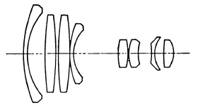
(a) The Voigtlander-Zoomar.
(b) The Auto-Nikkor.
(c) The Canon Zoom 35.
FIG. 5.38. Three zoom lenses. The broken lines represent movable elements.
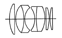
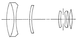
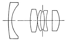
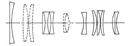
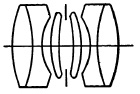
The first variable focus or zoom lens for still cameras, the Voigtlander-Zoomar, was placed on the market in 1959. It is designed for 35 mm. single-lens reflex cameras and has a focal length range from 36 mm. to 82 mm. and an aperture of f/2.8. There are fourteen lenses in five groups, two movable and three fixed (Fig. 5.38a). The movable lenses (broken lines) are connected and move as a unit. In the position shown the focal length is 82 mm. ; moving the movable lens unit to the right changes the focal length down to 36 mm. The lens is focused by a screw which shifts the front element. The definition is very good but not as good as that of first-quality lenses of fixed focal length. There is distortion of the pincushion type at the longer focal lengths and of the barrel type at the shorter focal lengths.
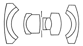
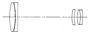
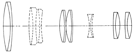
The Auto-Nikkor (Fig. 5.38b) has an aperture of f/4 and a focal length range from 85 mm. to 250 mm. The Canon Zoom 35 (Fig. 5.38c) has a focal length range from 45 mm. to 200 mm. at f/2.8. All of these lenses are for use with the 35 mm. single-lens reflex.
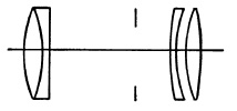
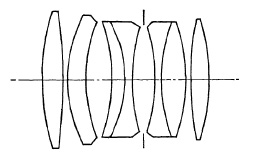
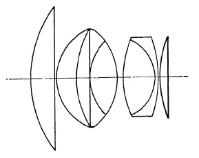
FIG. 5.39. The Petzval lens.
Portrait Lenses. The Petzval lens (Fig. 5.39), calculated by Josef Petzval for the firm of Voigtlander (Vienna 1840), was for nearly a century the standard lens of the professional portrait photographer. It was favored primarily for its large aperture; the definition near the axis is excellent but the field is sharply curved and the length of the lens causes considerable vignetting, with the result that both the definition and illumination fall off rapidly a few degrees from the axis. This makes the Petzval lens unsuited to groups and full figures, but many portrait photographers regard its curved field as an advantage for head and shoulder portrait since it is possible to have sharp definition on the face only and subdue detail progressively toward the margins. In recent years, however, the Petzval lens has given way to other types.
Many portrait photographers do not care for the sharp definition of a fully corrected anastigmat except for groups and full-figure studies. To meet their needs a number of anastigmat lenses intended for portrait photography are provided with means of softening the definition by moving one of the elements of the lens.
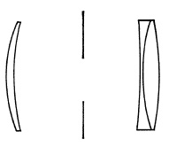
FIG. 5.40. Portrait lens of Wollensak.
Portrait lenses designed to produce a moderately soft, "plastic" image are made by several opticians (Fig. 5.40). These lenses usually are corrected for chromatic aberration and for a flat field, but purposely undercorrected for spherical aberration. The softness, or diffusion, of the image is controlled by the diaphragm which, by reducing the spherical aberration, produces a sharper image. In the Imagon of Rodenstock, sharpness is controlled by diaphragms which vary the proportion of the central and zonal light rays forming the image. This enables sharpness to be varied by changing the diaphragm without appreciably changing the exposure. Experience is required in focusing lenses of this type and in choice of diaphragm, and such lenses are more suitable for certain subjects than others.
It should be noted that the diffusion produced by lenses of this kind is quite different from, and much more pleasing than, that produced by screens and other diffusing devices. These merely diffuse the image or reduce contrast. The soft-focus lens, on the other hand, surrounds each bright point in the image with a halo which more nearly corresponds to the visual effect. It should be noted also that the use of a soft-focus lens in enlarging has the opposite effect: a dark halo surrounds the darker areas which is contrary to the visual impression.
For head and shoulder portraits the focal length of the lens should be at least 50% greater than the diagonal of the picture, and many professional photographers prefer lenses of longer focal length. If short focal length lenses must be used, the distance between camera and subject should still be from 6 to 10 ft. The image will be small but may be enlarged. Attempts to obtain a larger image in the negative can lead only to unpleasant drawing which overemphasizes the size of those parts of the subject nearest the camera.
Process Lenses. The term process is applied to copying lenses used in making negatives for photo-reproduction processes, such as photoengraving, photolithography, and photogravure. The process lens must have a flat field, uniform definition, and illumination over its field. As a copying lens it must be corrected for much shorter object distances than the ordinary camera lens. The focal length of process lenses is usually about twice the diagonal of the film with which they are to be used, and the maximum aperture ordinarily is from f/8 to f/10.
(a) Kodak Ektar.
(b) Goerz, Tri-Color.
(e) Schneider, Componon.
FIG. 5.41.
Process lenses in which the secondary spectrum is corrected are termed process apochromats. These are used for making three-color separation negatives and are preferred by many commercial photographers for color work in the studio, particularly where fine detail is involved.
Lenses for Projection Printing. Lenses for projection printing must give good definition on a flat field for the range of enlargement, or reduction, necessary. Camera lenses are corrected for much greater object distances than those used in projection printing and usually require considerable stopping down for good results. Since the image is focused visually, the lens must be well corrected for both longitudinal and lateral chromatic aberration.
Most enlarging lenses are four-element anastigmats of the tessar type, but recalculated to provide superior performance at shorter object distances than camera lenses of the same type. With the increasing use of 35 mm. cameras, and particularly with color, the need for better lenses has been recognized, and other designs, such as those shown in Fig. 5.41, have been employed. These, or process lenses, are to be preferred for color printing or for the best results in enlarging from 35 mm. negatives.
Lens Testing. So far as the testing of lenses is concerned, the average photographer has neither the equipment, patience, or know-how, to test a lens. Rough tests, such as photographing a brick wall can, if properly made, be helpful in determining if a lens is poor. Such tests require a firm tripod and, in the case of range-finder cameras, accurately measured distances. The negative should be made on ordinary not high-contrast film and developed in the usual way. High-contrast images give a false impression of definition. In all cases, the distance of the test object from the lens should compare with the conditions under which the lens will be used. Thus, photographs of small charts, or a newspaper, are misleading except as applied to copying lenses.
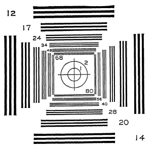
FIG. 5.42. Bureau of Standards lens test chart.
More definitive tests can be made by using test charts of the type shown in Fig. 5.42 placed at intervals from the center of the field to at least one corner and preferably diagonally in both directions. The images on the negative should be examined with a good hand magnifier, and the number of lines resolved in the center of the field and at different distances from the axis determined and recorded. The resulting record will enable the lens to be compared with similar records of other lenses.
Any test of a lens on a camera is necessarily a test of the camera as well as the lens. Thus tests made with a rangefinder camera show only the performance of the lens on that particular camera. A lens giving inferior results on one camera may be excellent on another. For the same basic reason, photographic tests of a lens with a ground-glass focusing camera may be undependable for any of the following reasons: a difference in the position of the ground-glass focusing screen and the film in the filmholder, lack of flatness in the film plane, the camera back not perpendicular to the optical axis of the lens, the lens not properly mounted on the lens board, inaccurate focusing, or differences in exposure and development of the negatives used as a basis of comparison.
A visual test of a lens may be made by examining the image of a test object on the ground glass at different distances from the axis with a low-power magnifier.
A test object for the purpose may be made by cutting an opening in the form of a cross in black opaque paper and placing this in a window open to the sky, or it may be placed on ground glass and illuminated by an electric lamp. The image should first be focused sharply in the center and examined carefully with the magnifier. Then the camera should be rotated about the lens as a pivot and the image of the test object examined, without refocusing, at different distances from the axis. The principal difficulty with a test of this kind is not that it lacks precision but that the interpretation of the result, in terms of photographic performance, requires experience that is beyond that of the average photographer.
Chromatic difference of magnification is a serious defect in a lens because it re sults in color fringes in color transparencies and blurring of the image in black-and-white photography. Color fringes can be detected on star images, or a test object which consists of a fine white thread on black velvet may be used. This test object should be well illuminated and placed so that the image of the thread is along one side of the focusing screen. If color fringing is seen when the image is examined with a good magnifier, the lens is not suitable for exacting color photography. Slight color fringing is usually of little concern in landscapes, portraits, and pictorial work in general. Lenses for enlarging may be tested for color fringing by projecting a negative of a line copy, focusing critically, preferably with a sharp focusing device, and examining for fringes.
Care of Lenses. Lenses should be protected from falls and sudden jars, from sharp changes in temperature, and from excessive heat and moisture. Exposed glass surfaces should be protected when not in use from dust and atmospheric gases by a lens cap, by keeping the camera closed or in a case. Despite these precautions, the outer surface of the lens will require an occasional cleaning. For this the special lens paper obtainable from opticians is recommended. If this is not available, a soft, clean linen handkerchief may be used. Avoid undue pressure, as some varieties of optical glass are quite soft and the polish may be affected. Solvents, such as alcohol, are best avoided, although those sold by opticians for cleaning lenses may be used sparingly. If a lens requires more than simple cleaning of the exposed glass surfaces, it should be returned to the maker for attention.
Cox, Optics, Focal Press, London and New York, 1956.
GREENLEAF, Photographic Optics, The Macmillan Co., New York, 1950.
Focal Encyclopedia of Photography, The Macmillan Co., New York, 1959.
HAEDY AND PERRIN, The Principles of Optics, Photographic Objectives, Ch. XXI, McGraw-Hill Book Co., Inc., New York, 1932.
KINGSLAKE, Handbook of Photography, Optics of Photographic Lenses, Ch. II; The Development of the Photographic Objective, Ch. Ill, McGraw-Hill Book Co., Inc., New York, 1939.
KINGSLAKE, Lenses in Photography, Garden City Books, Garden City, New York, 1951.
LOCKETT, Camera Lenses, Henry Greenwood & Co., Ltd., London, 1958.
MERTE, RICHTER, AND VONROHR, Die Photographische Objectiv, Vol. 1, Handbuch der Wissenschaftlichen und Angewandten Photographie, Springer, Vienna, 1932.
NEBLETTE, Photographic Lens Manual and Director, 3d Ed., Morgan and Morgan, New York, 1962.
1 For a list of commercial triplet lenses, see Neblette, Photographic Lens Manual and Directory, 3d Ed., Morgan and Morgan, New York, 1962.
2 For a list of commercial lenses of this type, see Neblette, Photographic Lens Manual and Directory, 3d Ed., Morgan and Morgan, New York, 1962.
3 The present Zeiss Planar f/2.8 is a different design. See text.