Don't forget to update your personal camera inventory
CollectiBlend
Antique and classic cameras/lenses price guide.CAMERAS
by C.B. Neblette.(c) 1952
Excerpt from the "Photography Its Materials And Processes" book (public domain according to the archive.org)
Fundamentals. The elementary camera consists of (1) a lens or pinhole to form an image; (2) a holder for the sensitive material; (3) a light-tight enclosure to prevent light from reaching the sensitive material except through the lens; (4) a shutter to control the exposure of the sensitive material; and (5) a means of determining what will be included in the picture.
The more advanced camera differs principally in providing means of focusing the lens. This may involve the use of a bellows, a mount which screws in and out, or the front element of the lens may screw in or out to focus the lens by changing its focal length. The bellows is used on large cameras; the screw mount chiefly on 35 mm. cameras where the distance the lens must move in focusing is short, and front-lens focusing on folding roll film and on some box cameras where the distance between the lens and the film is fixed. To determine when the image is in focus the camera may have (1) a focusing screen showing the image formed by the lens, as in studio and view cameras, the reflex, and the twin-lens camera; (2) a range finder which measures the distance and is coupled to the lens so that it is focused for the distance as measured by the range finder, or (3) a focusing scale marked in feet or meters. In this case the distance is estimated, or measured, with a separate range finder and the lens set for that distance on the focusing scale. The more advanced camera may provide for the use of different lenses, for changing from one type of film to another after each exposure through the use of separate filmholders, and it may have adjustments which enable the lens front, the back, or both, to be changed so that the film is no longer at a right angle to the optical axis of the lens (swing-back, swing-front). Since these adjustments can be used only when the image can be focused on a focusing screen and on a camera with a bellows, they are found only on studio and view cameras and the smaller press camera.
View Finders. In all cameras except those focused on the ground glass (twin-lens, reflex, and stand cameras) a finder must be provided to show what will be included in the picture. To be dependable, a finder must show exactly what will be included in the image. This is possible only if :
1. The viewpoint of the finder and the camera lens are the same;
2. The angle of view of the finder and the camera lens are equal ;
3. The axis of the finder and the camera lens coincide.
These conditions cannot be completely fulfilled by any view finder; however, in some modern types (to be discussed later) the departure is so small as to be insignificant for all practical purposes.
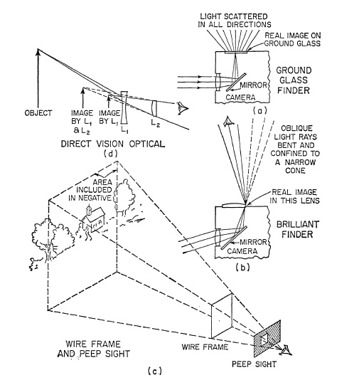
FIG. 7.1. Types of finders.
The simplest finder is a frame with a peep sight in the rear to position the eye (Fig. 7.1c). The frame may be small and close to the peep sight, or it may be as large as the picture itself and placed in the position of the lens, the peep sight being in the plane of the film. Such a finder, which is common on press-type cameras, has the advantage of showing quite well the variation in the field of the lens at different object distances.
Reflecting finders (Fig. 7.1a and 7.1b) were once widely used on box and folding roll-film cameras, but are now little used.
The typical optical view finder (Fig. 7.1d) consists of a front divergent lens which forms a small, erect, laterally correct image that is seen through a rear converging lens. This lens serves the dual purpose of enlarging the image and positioning the eye. Masks may be placed over the front to show the field included by lenses of longer focal length and the finder may be mounted so that it can be tilted, or the rear lens mounted so that it can be raised or lowered to compensate for the parallax error at different distances.
In the Albada finder the inner surfaces of the two elements are used to produce a frame which is seemingly superimposed on the subject. The concave inner surface of the front lens (Fig. 7.2) is lightly silvered to act as a mirror, and a frame is placed on the facing surface of the rear lens. The image of the frame then seems to float in space marking the field of the lens in a larger area which is clearly seen in the finder.
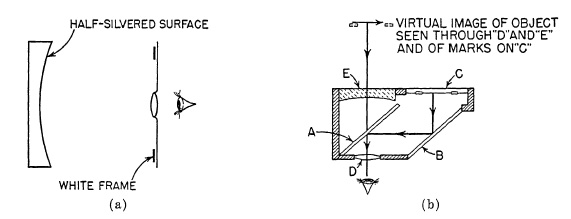
FIG. 7.2. (a) The Albada finder; (b) Modification of the Albada finder.
Finders on cameras equipped with range finders are usually combined with the range finder and will be discussed later.
Range Finders. The principle of the range finder is shown in Fig. 7.3a. One of two rays of light from a distant object is reflected at right angles on mirror A and then to a second mirror B, which reflects it to the eye. The other ray passes directly through the half-silvered mirror to the eye. Thus, although there are two images of the object, they are superimposed and appear as one. However, if the object is close, as in Fig. 7.3b, the two rays are no longer superimposed but are seen separately. However, by rotating mirror A, it is possible to superimpose the two images again. The amount by which mirror A must be rotated depends upon the convergence of the two rays which, in turn, depends on the distance of the object C. Thus, the distance of point C can be found in terms of the amount of rotation of mirror A required to superimpose the two images.
The reliability of a range finder depends upon the accuracy with which the angle at A is measured. The angle increases as the distance of the object C becomes less, so that a range finder is more accurate for short distances than for long. The angle at A increases also with the distance between A and B, the base of the range finder. Range finders must be instruments of optical precision if they are to be reliable, because the angle to be measured at A is always small. With a base of 2 in., for example, and an object distance of 10 ft., the angle to be measured is less than a degree; and, for an object distance of 20 ft., it is less than half a degree.
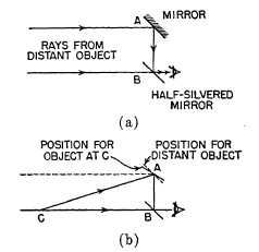
FIG. 7.3. Principle of the range finder.
The range finder is usually connected, or coupled, with the lens so that moving the camera lens through its focusing range rotates the prism A. Thus, when the two images are superimposed in the range finder, the lens is in focus for that portion of the subject. Coupling is usually accomplished by a lever ; one end of the lever is held by a spring against the rear of the lens mount and the other end controls the rotation of the free prism of the range finder. Thus as the lens screws in or out, this movement is transmitted by the lever to the rotating prism which, in turn, controls the position of the movable image in the range finder, A simple lever coupling cannot be correct for all distances; if the coupling is accurate for infinity, then it will not be accurate for near objects. The movement of the lens in focusing is controlled by the basic lens law while the movement required of the movable prism is governed by a trigonometric formula connecting the object distance u, the base of the range finder b and the angle the prism must move φ; u = b/(tan 2φ). The error is not great and can be avoided entirely by shaping the end of the coupling lever so that the movement of the prism is not in a constant ratio to the movement of the lens mount; i.e., through the use of a cam. The coupling mechanism of a well-known range-finder camera is shown in Fig. 7.4.
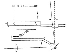
FIG. 7.4. Typical coupling mechanism of range finder to lens.
Two methods are employed in combined range and view finders to adapt the view finder to interchangeable lenses. One method is to include magnifying lenses in the view-finder system which can be introduced as required to change the size of the image in the finder to correspond to the focal length of the lens. The other, and more widely used, method is to introduce framing lines outlining the field included by different lenses. If several framing lines are visible at once in the finder, the effect can be confusing and in at least one camera each lens automatically introduces its own frame in the finder so that only the framing line applying to that focal length is seen in the finder.
A typical multiframe, parallax correcting, combined view and range finder is shown in Fig. 7.5 (Leica M3). Three images reach the eyepiece at the extreme left. One, on the left, is the direct beam of the range finder passing through the window, 1, the imaging lens, 2, the beam-splitter, 3, to the eye. The other range-finder image, at the far right, passes through the window, 4, the pentaprism, 5, the swinging lens, 6, to the prism, 7, where it is reflected to prism, 8, thence through the magnifier, 9, to the reflecting surface of the beamsplitter, 3, where it is reflected to the eyepiece and superimposed on the direct image from 1, 2, and 3. The light admitted through the frosted window in the center, 10, illuminates the framing masks, 11, passes on to the prism, 8, to the beamsplitter, 3, and thence to the eye. As lenses are changed a mechanism, which is not shown in the illustration, moves the frame selector to the proper position for the 50 mm., 90 mm., or 135 mm. lens. The coupling to the lensmount moves lens, 6, as shown by the arrows shifting the comparison image of the range finder and moves the frame, 11, as shown by the arrows, to compensate for parallax.
Range-Pinder Cameras. Although there were earlier cameras making 1 X 1.5 in. pictures (24 X 36 mm.) on motion picture film, the first of importance was the Leica which was designed by Oskar Barnack and placed on the market in 1924 by E. Leitz, of Wetzlar (Germany), manufacturers of microscopes and other precision optical instruments. The Leica was regarded skeptically by most photographers, but the work of Dr. Paul Wolff, and others, soon demonstrated that it was no toy but a camera which opened up new fields of photography. Professional photographers were amazed at the sharpness of the small negatives, and both the amateur and the photo- journalist saw in the new camera a new and exciting approach to photography that was free from the limitations of the older and larger cameras.
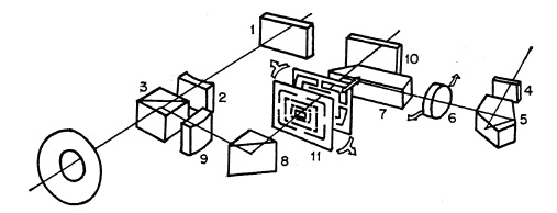
FIG. 7.5. Optical system of a typical multiframe, parallax correcting, combined range and view finder.
The first Leica had a focal-plane shutter which was connected to the film movement so that the film is changed and the shutter set in one operation. This prevented double exposures and it was no longer necessary to watch for numbers in a window at the back of the camera. The film, without a paper backing, was contained in daylight-loading magazines. After the 20 or 36 exposures had been made, the film transport mechanism was reversed and the film wound back into the magazine which could then be removed from the camera in daylight. The lens, in a screw-focusing mount, was provided with focusing and
depth-of-field scales. The whole camera was constructed with a precision unknown up to that time. The first Leica did not have a range finder. The range finder coupled to the lens for direct focusing appeared on the Leica in 1931 and the Zeiss Contax in 1931-1932. There have been no basic changes in design since then but many improvements. Many of these have been essentially improvements for greater ease in use, but important advancements have been made in view finders, in the introduction of interchangeable lenses, and in the variety and the quality of the lenses for this type of camera. The f/3.5 lenses have been replaced by f/2 and f/1.5 lenses, and larger, of excellent quality, wide-angle lenses and long-focus lenses. Greater progress has been made in optics for the 35 mm. camera than in any other size. In view finders the progress has been equally great from the small image of the earlier cameras to the 1:1 image, or in some cases larger, to the combined view and range finder, to the framing line finder eliminating the errors arising from the improper positioning of the eye, correcting for parallax and adaptable to lenses of different focal length. Parallax correction is accurate only for the distance for which the lens is focused; it is not corrected for objects at other distances but the difference is unimportant except for subjects which have objects very close and at a considerable distance from the camera.
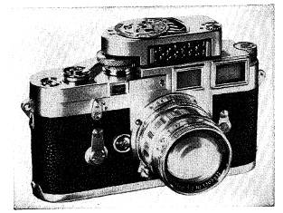
(a) With focal-plane shutter (Leica M3).
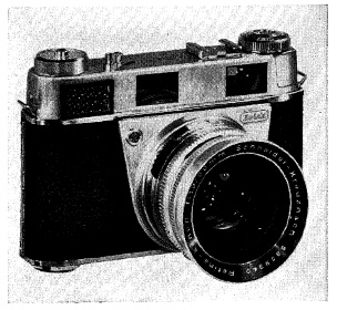
(b) With rear diaphragm shutter for interchangeable lenses - (Retina III).
FIG. 7.6. Typical 35mm. range-finder cameras.
Range-finder focusing is more accurate than ground-glass focusing, particularly with small images, provided (1) the range finder is accurate; (2) the coupling mechanism functions properly; (3) the lens is fitted properly to the coupling mechanism, and (4) the objective is to focus on an object at a given distance. If the problem is to obtain sharp focus with objects at different distances from the lens, the range finder can be used to measure the extreme distances and the point on which to focus, and the lens aperture required can be determined from the depth of field scale on the lens mount. Any superiority of range-finder focusing is dependent, however, on accurate coupling of the lens to the range finder. This must be done with a high degree of precision, particularly with large aperture or long-focus lenses. The requirement for accurate coupling to the range finder makes interchangeable lenses for the range-finder camera more expensive than lenses for the reflex or other ground-glass focusing camera, and is one reason for buying only the best, preferably those made by the manufacturer of the camera. Lenses which are not properly adjusted for use with a particular camera can, in many cases, be made so by a competent repairman.
Long-focus lenses, usually those with a focal length greater than 180 mm., do not couple with the range finder but must be used with a reflex attachment which, in effect, converts the range-finder camera into a single-lens reflex.
The need for interchangeable lenses is greater with 35 mm. cameras than with larger cameras because the small negative size does not offer the same opportunity for cropping and the use of only a portion of the negative. For projected prints of good quality, it is highly desirable necessary if the print is large to be able to use the whole negative. Fortunately the design of the 35 mm. camera and its size make the interchanging of lenses more convenient than any other camera.
The range-finder camera with interchangeable lenses may employ a focal-plane shutter, an interlens-type shutter mounted behind the lens, or a lens shutter with a lens in which interchangeability is obtained by changing only the front portion of the lens (Fig. 7.6). The focal-plane shutter has the advantage of enabling both wide-angle and long-focus lenses of the conventional types to be used.
The lens can be mounted close to the focal plane and, since the shutter is close to the film, the rear exit aperture of the lens may be as large as the film. When an interlens-type of shutter is mounted behind the lens, a shutter with high opening and closing speeds is necessary to prevent vignetting. To achieve this (and keep the size of the shutter within reasonable limits) lenses of special design with relatively small rear components are necessary. The distance of the lens from the film plane is such that wide-angle lenses must be of the inverted telephoto type. The requirement that the rear lens component be kept small limits the maximum aperture for both wide-angle and long-focus lenses. Extension tubes or bellows attachments cannot be used for close-up work with cameras having lens shutters. With these, supplementary lenses must be used instead.
The major disadvantage of the focal-plane shutter is the limitation on the use of electronic flash. With most 35 mm. cameras the highest shutter speed that can be used with electronic flash is about l/60th of a second. This usually is unimportant where the flash is the sole source of illumination, or the only source of importance, but becomes important where the flash is used in combination with other sources as, for example, as a fill-in light on outdoor subjects.
Interchangeable lenses of the type in which the front portion only is changed are produced by Zeiss, by Schneider, and by Rodenstock. The range in focal length is limited and the apertures, for all but the standard lens, are relatively small. The performance of such lenses is quite good, but does not equal that of conventional lenses of the highest quality. Close-up work is possible only with supplementary lenses.
The 35 mm. camera is a far more capable instrument today than it was a decade ago. The progress in emulsions has practically eliminated the graininess and lack of critical sharpness which was characteristic of much 35 mm. work a few years ago. Now only good technique is required to produce results which can compare with the larger camera and may, in many cases, be better.
Good technique involves (1) accurate focusing, (2) avoidance of camera movement during the exposure, (3) proper choice of emulsions, (4) correct exposure, (5) proper developer and careful attention to temperature of processing solutions, proper agitation, and mechanical handling of film to avoid physical damage. Camera movement during exposure is one of the most frequent sources of unsharp results. The 35 mm. camera is far more critical in this respect than the larger camera because of the greater degree of enlargement in the final print. As a general rule it is best to use the largest aperture that can be used, consistent with the requirements for depth of field. This is particularly the case if the smaller aperture requires exposures longer than l/100th of a second.
A few folding roll-film cameras have coupled range finders, notably the Super Ikonta of Zeiss (2¼x2¼). These larger cameras, however, do not have interchangeable lenses.
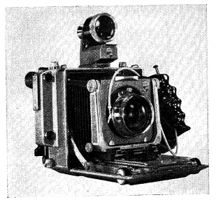
Press Cameras. Cameras of the type shown in Fig. 7.7, are in wide use by press photographers and the advanced amateur. While these have ground-glass focusing, they also have a coupled range finder. This type of camera with coupled range finder and interchangeable lenses combines much of the mobility and convenience of the 35 mm. camera with a larger negative (2¼x3¼, 4x5 inches). With lenses of the focal lengths used with these cameras, it is necessary, however, to have a different coupling link, or cam, for each lens. Thus both the lens and the cam must be changed so the operation is not quite as simple as with the 35 mm. camera. This, however, is only minor inconvenience. The press-type camera is in many ways a more versatile camera than the 35 mm. of any type. Not only does it have interchangeable lenses, a coupled range finder, and a parallax-correcting finder, but it has the rising front, tilting front, and adjustable back of the stand camera. These adjustments, however, can be used only if the camera is placed on a tripod and the image focused on the ground glass. Although designed primarily for sheet film in holders, film packs in adapters and roll film in roll holders may also be used. Thus there is complete interchangeability from one negative material to another in any form, sheet film or roll film, between each exposure.
(a) Linhof Technika
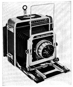
(b) Graphic
FIG. 7.7. Typical hand-press cameras.
The Reflex Camera. The principle of the reflex camera is shown in Fig. 7.8. The image formed by the lens is reflected by a mirror to a focusing screen at the top of the camera. When an exposure is made, the mirror swings up to clear the lens and cover the focusing screen. The focal-plane shutter is then released automatically to make the exposure. The mirror is then returned to its original position by a lever on the outside of the camera and the shutter reset for the next exposure. In this form the reflex has been made for many years. After World War II the real development of the reflex began. The first step was the addition of an erecting prism to produce an upright, nonreversed image with the camera at eye level. This was followed by a design employing a lens shutter instead of the focal-plane shutter, thus extending the reflex camera to use with electronic flash at all shutter speeds. Finally, the automatic diaphragm was developed. This made it possible to set the aperture to be used for the exposure in advance, the lens remain ing at full aperture for focusing and for viewing the image until the actual exposure.
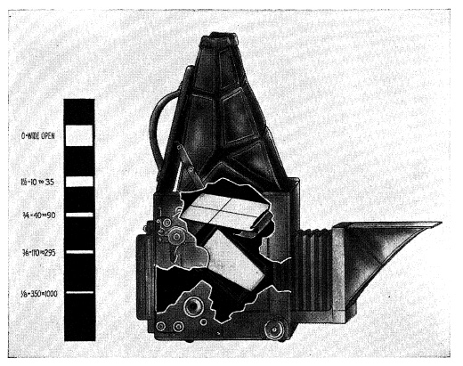
FIG. 7.8. Principle of the reflex camera.
There are two types of automatic diaphragms. In one (fully automatic) the diaphragm closes down to the preset aperture just before the exposure and reopens immediately after the exposure to full aperture. In the other type the diaphragm reopens when the shutter is set for another exposure. In some cases, the automatic diaphragm control is on the outside of the camera separate from the lens mount; in other cases, it is internal being operated from the shutter release. Some automatic diaphragms have the disadvantage that it is impossible to stop down the lens when focusing to determine the depth of field from the ground glass. This is more often the case on cameras using lens-type shutters.
The choice between the 35 mm. reflex with a pentaprism and a 35 mm. camera with a range finder is largely a matter of personal preference. The reflex has the advantage of being completely free of parallax for all objects included in the field of view regardless of their distance, which is a decided advantage with close-ups. If it is possible to focus at other than the maximum aperture (not all reflexes with automatic diaphragms have this advantage), the depth of field can be seen on the focusing screen and also the degree of unsharpness of the areas beyond the range of sharp definition. This may be of considerable interest to the pictorialist who wishes to use differential focusing for different planes of the subject. The range finder of the single-lens reflex (and again not all have this feature) is inoperative at small lens apertures but does have the advantage of being accurate for any lens. If the reflex does not have a range finder, focusing is less likely to be as accurate, particularly in poor light, as with a range-finder camera. Wide-angle lenses for the reflex must be of the reversed telephoto type which is larger, usually more expensive, and more subject to distortion than the conventional types used on range-finder cameras. There is frequently some vignetting on the focusing screen with long-focus lenses, but not on the film.
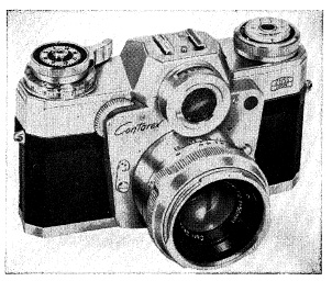
(a) 35mm. reflex with focal plane shutter (Zeiss Contarex).
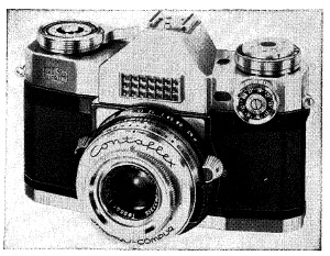
(b) 35mm. reflex with lens shutter (Zeiss Contaflex).
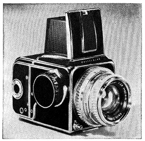
(c) 2¼x2¼ reflex with separate film magazine (Hasselbad).
FIG. 7.9. Modern reflex cameras.
Reflex cameras are available in larger sizes, for example, 2¼x2¼, 2¼x3¼ and 4x5 in. These, like press camera, have interchangeable backs permitting the use of sheet film in holders, film packs in adapters or roll film in roll-film magazines, as preferred for each exposure. Most of these larger cameras do not have an erecting pentaprism because of its weight and cost; in some cases it is available separately. Generally, these larger cameras have focal plane shutters, the Hasselblad (Fig. 7.9) being an exception. It has interchangeable lenses mounted in lens shutters each with its own automatic diaphragm.
The Twin-Lens Camera. The basic design of the modern twin-lens camera was established by the Rolleiflex, introduced by Franke and Heidecke of Brunswick (Germany) in 1929 (Fig. 7.10). The construction results in a compact, handy camera with the viewing and camera lenses placed close together to minimize parallax. The viewing lens produces an upright, but laterally reversed image, for focusing and composing the image. It is usually of simple construction with a larger aperture than the camera lens for a more brilliant image. A 3-4x magnifier is mounted in the hood of most cameras as an aid to more accurate focusing, and split-field range finders mounted on the ground glass are available as an accessory.
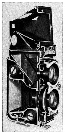
FIG. 7.10. The twin-lens camera.
An erecting prism for eye-level operation is also available as an attachment for some cameras. The camera lens ordinarily is either a triplet or "tessar" type with an aperture of f/3.5. Close matching of the focal lengths of the viewing and camera lenses is obviously important to accurate focusing. Low-priced cameras often show greater tolerances in the matching of the lenses than the top quality instruments.
The parallax resulting from the separation of the viewing and camera lenses is unimportant except for subjects close to the camera. The Rolleiflex has a mask over the focusing screen which is connected to the lens front with a link lever. As the lens is focused the mask moves across the focusing screen to compensate for parallax. The field shown on the focusing screen is correct, however, only for the distance on which the lens is focused. Special parallax-correcting lenses, for use over the viewing lens, are available for close-up work with supplementary lenses. Supplementary lenses are necessary for close-up work because the closest working distance with most twin-lens cameras is from a meter to 3½ ft. Parallax may also be corrected, with still-life subjects, by composing the subject on the focusing screen and then raising the camera a distance equal to the separation of the centers of the two lenses.
The twin-lens camera is a less versatile instrument than either the 35 mm. range-finder camera or the reflex, but it is simple, convenient, and dependable for general photography. These qualities have made it one of the more popular types for the amateur and the photo-journalist.
Sub-Miniature or Ultra-Miniature Cam eras. Cameras using film smaller than 35 mm. are usually referred to as sub-miniature or ultra-miniature. The oldest of these, the Minox, uses a 9.5 mm. film for pictures 8 X 10 mm. Most later cameras are designed for 16 mm. film and the picture size varies from 10 X 10 mm. to 12x17 mm. The ultra-miniatures resemble the 35 mm. camera except for the Minicord, which is a twin-lens camera. Interchangeable lenses are available for some models.
The depth of field is so great with the short focal-length lenses on these cameras that many do not have a coupled range finder.
Used with modern, thin-emulsion, fine-grain films, these small cameras are quite capable of enlargements up to about 5x7 in., or even 11x14 in. with certain subjects.
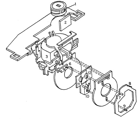
FIG. 7.11. Automatic exposure control on Kodak Automatic 35.
Cameras with Automatic Exposure Control. The first camera in which the exposure was controlled automatically by a photoelectric cell was placed on the market by the Eastman Kodak Company in 1938 as the Kodak Super 620. It was in advance of its time and was discontinued with the advent of World War II.
The first step in the chain of events which was to result in the automatic camera of today was the introduction of the Light Value System (LVS) on new models of the Compur shutter placed on the market by Deckel, of Munich. From this it was but a logical step to semiautomatic control. In cameras with semiautomatic control, the exposure meter built into the camera is first set for the film in use. The shutter is then set for the desired shutter speed. Changing the aperture moves a pointer in the dial of the exposure meter. When this pointer coincides with the pointer of the exposure meter, the camera is set for the proper exposure. If the photographer wishes to use a different aperture, he changes the shutter speed and brings the two pointers together as before. On some cameras the exposure control can be affected by changing either the diaphragm or the shutter speed. When either is locked, changing the other will move the pointer on the dial of the meter to indicate the correct exposure.
The controls of the Kodak Automatic are shown in Fig. 7.11. Setting the film and shutter speed controls the position of the diaphragm (1) which covers the photocell (2). The current generated by the cell operates the meter (3). The pointer of the meter (4) swings in direct proportion to the current from the photocell which, of course, depends upon the light reflected from the subject. When the exposure is made with the shutter release (5), a spring lifts the yoke (6) and frame (7) until the cam (8) just touches the meter needle (4). The pin (9) moves up with the frame in slot (10), controlling the size of the aperture in the diaphragm (11, 12). As soon as the cam touches the meter needle it stops and the aperture is correct for the meter reading. When this sequence has been completed, the shutter is released and the exposure made.
The Polaroid Electric Eye camera uses a cadmium sulfide photoconductive cell powered by a small battery instead of the self-generating photocell of the other meters. The light on the photoconductive cell controls the amount of current transmitted by the cell to a galvanometer. The galvanometer is connected mechanically to the diaphragm and shutter controls so that these are set automatically from the galvanometer. The advantage of the photoconductive cell is its greater response at low illumination levels.
The Stand or View Camera. The stand camera is the instrument of the deliberate photographer the camera of the planned picture. It is the most versatile camera for all subjects which are essentially static, such as landscapes, architecture, interiors, and most kinds of technical photography.
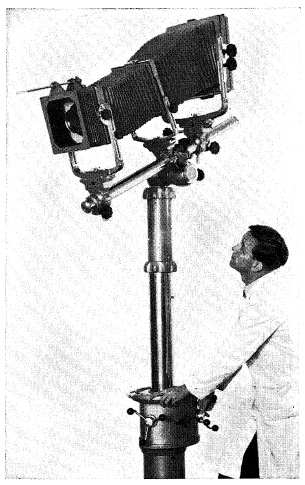
(a) Linhof.
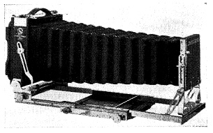
(b) Deardorf.
FIG. 7.12. Typical stand cameras.
The principal features of the view or commercial camera (Fig. 7.12) are:
1. A long bellows for close-ups, copying, or for long-focus lenses: usually three times the focal length of the normal lens.
2. A rigid bed to maintain parallelism between the front and back of the camera when the bellows is fully extended or heavy lenses used. The monorail bed is exceptionally rigid; however, it does not fold up as conveniently for carrying as the telescoping or sectional bed.
3. A large, substantial front for large and heavy lenses, and having one or more of the following movements:
(a) a rising and falling front which permits the lens to be raised or lowered to include more at the top or the bottom of the picture;
(b) a sliding front which enables the front to be moved to the right or the left;
(c) a vertical swing which enables the lens to be tilted upward or downward.
The pivotal point is preferably about the optical center of the lens but on some cameras, for mechanical reasons, the entire front is inclined from the camera bed.
4. A large lens board, easily removed to change lenses.
5. Large focusing controls with locking device.
6. (a) A back with a vertical swing (i) so the back can be kept in a vertical position when the camera is tilted up or down to include all of the subject; (ii) to obtain sharp definition on objects at different distances with larger aperture, and (iii) to control the relative sizes of near and distant objects, (b) A back with a horizontal swing, which serves the same purposes in a horizontal direction, (c) Less frequently, a sliding back and a rising and falling back which serve the same purpose as the corresponding movements on the camera front. The back is reversible, for vertical or horizontal pictures, and the ground glass focusing screen has springs so the filmholder can be inserted without removing the focusing screen. The focusing screen of some view cameras is provided with a hood, but usually a focusing cloth is assumed. The focusing controls provide for focusing from the rear as well as from the front.
The view camera is designed for use on a tripod and, therefore, has no finder nor focusing scale. It is intended for sheet film in holders; however, in the smaller sizes roll-film adapters are available. The common sizes in the United States are 4X5, 5x7, and 8 X 10 inches; however 2¼x3¼ cameras are available and one using 35 mm. film.
Optical Problems Related to the Stand Camera. The increased freedom of lens and film movement necessitates a re-examination of the optics involved because, unless thoroughly understood, these may be the source of much confusion, and improper use may defeat the purpose for which they are intended.
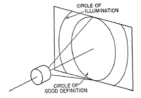
FIG. 7.13. Circles of illumination and good definition.
The field of view of a lens is circular in character and this may be seen if a lens of relatively short focal length forms an image on a large ground glass. The larger circle, as in Fig. 7.13, is often called the circle of illumination. It is limited in size because, since corrected lenses are thick, light from beyond a certain angle is cut off, or vignetted, by the lens mount. The circle of illumination is almost always larger in diameter than the circle of good definition, sometimes considerably larger. The size of the circle of good definition depends upon the design of the lens. In almost all cases the size of this circle increases as the aperture of the lens is decreased, until in some cases the entire circle of illumination is filled with good definition. It is usual to measure the size of these circles in terms of the half-angle of the cone formed by the circle as base, with its apex at the center of the lens, as illustrated in Fig. 7.14. Sometimes the whole angle is used, and, therefore, it is good practice to specify just what angle is meant. It is important to remember that the cone of light, within which a sharp image is formed by the lens, acts much as if it were fastened rigidly to the lens.
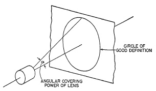
FIG. 7.14. Angular covering power of a lens.
As the lens is moved up and down (rising front), or is displaced sideways, the image also moves. If the subject is far away, the image moves the same amount as the lens and in the same direction; in other words, it moves with the lens. Where the object is only a few focal lengths distant, the image moves more than the lens so that the movement b of the image is equal to a((u+v)/v) where a is the lens motion, and u and v are the image and object distances. This relation may be seen from Fig. 7.15.
So far it has been assumed that the plane of the film is always at right angles to the optical axis of the lens and that the principal objects are also, in general, perpendicular to this axis. In the stand camera both lens and film may be tilted. Actually, if parallel lines in the object are to be parallel on the film, the film plane must be made parallel to the object plane containing the lines, and both must be perpendicular to the lens axis.
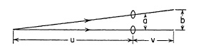
FIG. 7.15. Relative movement of lens and image.
There is, however, a much more general relation between image and object plane than this. For any plane on the object side of the lens, there is a corresponding plane on the image side of the lens in which the object is in sharp focus, as in Fig. 7.16. In this case, lines which are straight in the object remain straight in the image, but the shape of the image is no longer the shape of the object. This results from the fact that different parts of the object are at different distances from the plane of the lens, which in turn means that different parts of the image are magnified by different amounts. In Fig. 7.17, A'B' = AB*v1/u1, but C'D' = CD*v2/u2, and since by inspection u2 is greater than u1 and v2 is less than v1, v2/u2 must be less than v1/u1. Therefore, since AB and CD are the same length, C'D' must be less than A'B'.
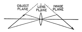
FIG. 7.16. General position of object, lens, and image planes.
There is a fixed and reasonably simple relationship between the plane of the object, the plane of the sharpest image, and the plane of the lens (i.e., the plane through the optical center of the lens at right angles to the optical axis). This is shown in Fig. 7.16 from which it will be seen that the planes containing the object, lens, and image meet in a line which is at right angles to the plane of the paper.
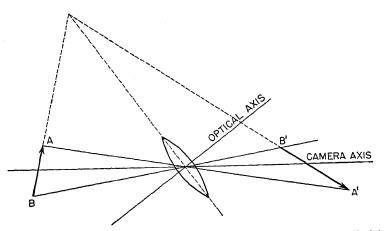
FIG. 7.17. Relation of image and object planes for best definition.
Under such circumstances it is very important to note where the optical axis of the lens points and to remember that the lens still covers with sharp definition only the same angular field as in normal use. In Fig. 7.17 it will be evident that object and image are far from being centered about the axis; and, unless the lens used has a wide field of good definition, the image near A' may be poor. This is true in spite of the fact that objects, lens, and image seem to be lined up along XY, which may be considered as the camera axis.
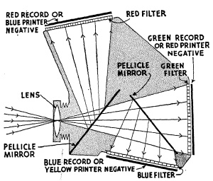
FIG. 7.18. Optical system of tricolor camera.
Special-Purpose Cameras. In one type of panoramic camera a spring-driven motor, controlled by a governor, revolves the camera on the tripod and winds the film on a receiving spool. The exposure is made through a slit across the film, the film moving past the slit at exactly the same speed as the image moves, so that as the camera revolves it photographs the different parts of the subject in succession.
In a second type, the lens is pivoted over the rear principal point and swings through a portion of a circle during the exposure, forming an image through a slit on a film curved in a partial circle.
Tricolor ("one shot") cameras for making three color-separation negatives employ reflecting-transmitting mirrors to expose the three negatives at the same time through a single lens.
In the double-mirror camera (Fig. 7.18), one image is formed by the light transmitted by the two mirrors; the other two images by reflection. The partially reflecting-transparent mirrors are made of thin plastic film stretched over an optically flat metal frame. These are called pellicle mirrors and, in some cases, are partially metalized to increase the amount of light reflected.
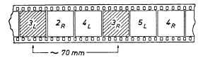
FIG. 7.19. Placement of stereo pairs on 35mm. film.
Tricolor cameras have been almost completely superseded by multilayer color films.
A stereo camera consists essentially of two identical cameras mounted side by side with all controls interconnected for operation of the two cameras as a single unit. The two images must be identical except for the differences due to their separation. Thus, the lenses must be matched in focal length and aperture, with the optical axes parallel and the two images exposed alike and, for objects in motion, at the same time.
All American-made stereo cameras use 35 mm. film, the picture size being 24 mm. high and 23 mm. wide (0.95x0.87 in.). The separation of the two lenses is usually approximately 70 mm., and there are two pictures belonging to other stereo pairs between the left and right images of the same stereo pair (Fig. 7.19).
ADAMS, Camera and Lens., Morgan & Morgan, New York, 1948.
EMANUEL AND MATHESON, Cameras The Facts, Focal Press, London, 1961.
KEPPLER, The Eye-Level Reflex, Amphoto, New York, 1961.
LIPINSKY, Miniature and Precision Cameras, Iliffe & Sons, Ltd., London, 1955.
MORGAN, Graphic and Graflex Photography, Morgan & Morgan, New York, 1954.
MORGAN AND LESTER, The Leica Manual, Morgan & Morgan, New York, 1961.
WALLS, Camera Techniques, Focal Press, London, 1954. WOLBARST, Pictures in a Minute, Amphoto, New York, 1959.