Don't forget to update your personal camera inventory
CollectiBlend
Antique and classic cameras/lenses price guide.PHOTOGRAPHIC SHUTTERS
by C.B. Neblette.(c) 1952
Excerpt from the "Photography Its Materials And Processes" book (public domain according to the archive.org)
Types of Shutters. There are two basic types of shutters in use today, the between-the-lens shutter and the curtain or focal-plane shutter. As the name implies, the between-the-lens shutter is located in an air space between the lens elements. This is the optically correct position. On a number of 35 mm. cameras, however, the shutter is placed directly behind the lens, so that lenses may be interchanged. The behind-the-lens shutter is basically the same as the between-the-lens shutter except for its position in relation to the lens. The focal-plane shutter is directly in front of the sensitive material. A slit in an opaque curtain running between two rollers admits light as it passes over the sensitive material to make the exposure.
Each of these two types has its merits and shortcomings, making each particularly adaptable to specific photographic tasks, to be covered in later discussion.
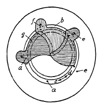
FIG. 6.1. Blade operation in a lens shutter.
Blade Movement. In between-the-lens shutters the light is admitted by the opening and closing of blades made of thin material shaped and arranged to open from and close toward the center. For this reason between-the-lens shutters are sometimes called central shutters. Whereas cheap and simple shutters have only one or two blades with holes, which are driven across the lens aperture, better shutters usually have from three to six blades, hinged about pivots and moved by pins closely adjacent to these pivots.
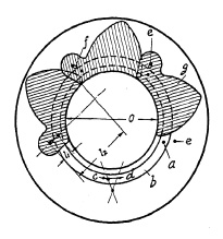
FIG. 6.2. Blades open.
Blade operation is illustrated in Fig. 6.1. Five pivots a are mounted in a blade ring b which can be turned freely in both directions c and d. Pins e are mounted in a plate corresponding to the number of blades (in this case five) and slots f are provided in the blades g to control the movement of these blades. In Fig. 6.1 the blades are shown closed. If the blade ring is rotated in direction c, pivots a will force the blades to a rotating movement whereby slots f will slide around pins b until the blades are in the "open" position, admitting light freely through the aperture "O" (Fig. 6.2). Fig. 6.3 shows the blades in half open position whereby a star-shaped, small opening is formed, characteristic of all central shutters with more than two blades. The ratio between the length l1 and l2 (Fig. 6.2) explains why a relatively short movement of the blade ring pivot a will cause the relatively long opening movement of the blade within a very short time interval. Movement of the blade ring in one direction c will open the shutter, and movement in the opposite direction d closes it. Consequently, one full operating cycle of the shutter consists of ring and blade movement in one direction, stoppage of that movement, and then reversal. This acceleration, stoppage, and reversal of the masses consume time and energy, and place limitations on the speed obtainable from this type of shutter. Attempts have been, and are still being, made to overcome these limitations.
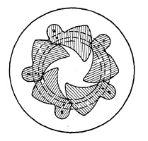
FIG. 6.3. Blades half closed.
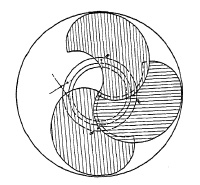
FIG. 6.4. Shutter with double-ended blades.
The Diaphragm. In very simple shutters, the diaphragm consists of a disc, or strip, of metal with two or three holes of different diameter. In most shutters, however, an iris diaphragm is employed. The name "iris" diaphragm is derived from its resemblance to the iris in the human eye which enlarges and contracts concentrically, with the intensity of the light. The iris diaphragm consists of from 5 to 12 (or more) leaves which can be opened or closed by turning an indicator on the outside of the shutter case. The greater the number of diaphragm leaves, the more nearly will the aperture approach the shape of a perfect circle, although there is no actual need for a perfectly circular opening.
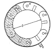
FIG. 6.5. Detail of iris diaphragm (open).
The technical elements and their principal arrangement in an iris diaphragm are shown in Fig. 6.5, illustrating a six-leaf diaphragm. These arc-shaped leaves are fastened to rotate about pins a mounted circularly in the case. Above the leaves a movable ring may be placed, slotted to receive pins b on the opposite end of the leaves. By turning this ring, pivots b engaged by the slots, force the leaves to rotate about pivots a, thus increasing or decreasing the size of the diaphragm opening.
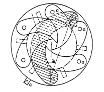
FIG. 6.6. Detail of iris diaphragm (partly closed).
Figure 6.5 shows the diaphragm at full aperture. By turning the ring clockwise, the diaphragm opening is reduced and is shown at minimum aperture in Fig. 6.6. The ring is usually connected with outside indicator c which moves over corresponding aperture "stop/numbers" on the face plate of the shutter. A large number of leaves requires greater axial space. High-speed lenses usually allow only a small air space between front and back elements; hence fewer leaves are preferred in modern shutters.
Source of Energy in Between-the-Lens Shutters. The blade movement (opening and closing the shutter) needs a source of energy, or motor, which in practically all shutters consists of a spring to be wound up before every operation. This winding-up, called "setting" or "cocking" the shutter, is a separate operation in all pre-set shutters. In automatic shutters the spring winding is performed by the same lever that releases the shutter, thus combining setting and releasing into one operation. The release operation of the shutter must be smooth to avoid jarring the camera. For this reason the combined set-and-release operation cannot cope with springs requiring great winding effort.
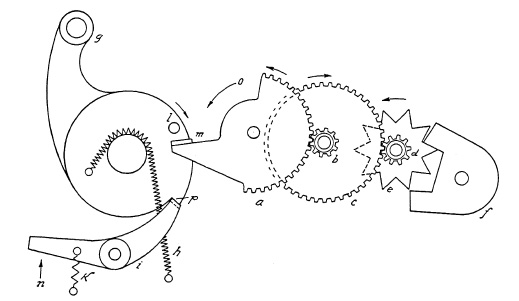
FIG. 6.7. Winding mechanism in a pre-set shutter.
Therefore, automatic shutters do not yield speeds as high as those of the pre-set shutter which can be built with stronger springs. A sketch of a winding mechanism in a pre-set shutter is shown in Fig. 6.7. To hold the wound-up spring h in its set-position a latch-lever i snaps into a latch p of set-lever g. When the release-lever or trigger (not shown) actuates latch-lever i in the indicated direction n, the wound-up set-lever g returns (clock-wise) to its original position under the driving power of spring h, actuating suitably arranged levers (not shown) which operate the reciprocating movement of the blade ring, thus opening and closing the shutter as previously described.
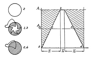
FIG. 6.8. Graphical representation of shutter operation at maximum speed.
Fig. 6.8 represents a graphic interpretation of a complete shutter-operating cycle at maximum speed. It is assumed (1) that the opening time is 2¼ milliseconds (one millisecond is 1/1000th of a second), (2) that the closing operation requires the same, and (3) the blades stay open for only ½ millisecond. A shutter with double-ended blades, as shown in Fig. 6.9, has no stopping or reversing action, and closes directly after the open period. Obviously, it must be possible to take a picture using a longer exposure time, with full aperture. Hence, the only period in the entire shutter operating cycle to be retarded for longer exposure time is the fully open period (time T2 in the example of Fig. 6.8, lasting only ½ millisecond).
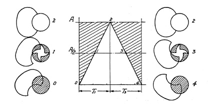
FIG. 6.9. Graphical representation of shutter with double-ended blades.
Retarding Mechanism. To obtain a range of speeds, a retarding mechanism is required. A well-designed retarder must
1. Slow down the shutter mechanism during the wide open period.
2. Be easily adjustable to the speeds required.
3. Provide speed settings which can be uniformly repeated.
During the evolution of the shutter in the past sixty years many different kinds of retarding devices have been used, from simple friction devices to air brakes. Many of these proved unreliable because of changing conditions due to wear, temperature, and climate. Temperature change, for example, influences density of the air and with it the retarding power of the air brake. The wheel retarder, which is not influenced by temperature changes, has superseded all other retarders. Its principle is relatively simple. A rotating movement is transformed into short oscillating movements of an element of relatively heavy weight. The inertia of this oscillating weight retards the driving movement, similar to the action of an escapement in clocks and watches.

FIG. 6.10. Two phases in the functioning of the retarding mechanism of a lens shutter.
The oscillating element is called a "pallet", and its oscillation is the result of its coordinated movement with a star-shaped ratchet wheel; Fig. 6.10 demonstrates the two phases of a pallet functioning as retarder. A star wheel a fits into the jaws b and b' of a pallet c in such close coordination that its rotation (indicated in counterclockwise direction by arrow e) pushes the pallet out of its way (position A). Simultaneously the other jaw b' of the pallet is moved into the path of the star wheel (position B). The star wheel, always driven in the same direction, now repulses the pallet from its path to the opposite direction, thus causing the oscillating movement of the pallet, in turn retarding the star wheel which might otherwise rotate freely. The retarding power of such a device can be increased by increasing the weight of the pallet, or by increasing its inertia by giving it special shape, or by imparting greater frequency to the oscillating movement. Of these three factors, faster oscillation exerts the greatest influence on retardation. This is the reason why the star wheel is located at the end of a gear-train in all shutters.
Figure 6.7 shows such a gear-train with star-wheel and pallet. If the first wheel a has, for example, 50 teeth, and the pinion on axle b has 10 teeth, one rotation of wheel a will cause 5 times as many or 5 rotations of axle b. On the same axle b there is another wheel c with 50 teeth driving axle d also with a 10-tooth pinion. The same gear ratio will drive axle d five times as fast as axle b and 25 times as fast as axle a. Now assume that the star wheel e on axle d has 10 teeth and rotates 25 times in the same time interval during which gear a has turned only once. Since every star-wheel tooth entering the jaws of the pallet f causes a single oscillation, the pallet will oscillate 250 times for every one turn of gear a, based on the established ratio, thus resulting in considerable retardation. In actual practice, the first wheel usually does not make a complete revolution. The arm m of the first gear a, hit by pin 1 of spring-driven set lever, or motor member g sets the entire gear train in motion. The retarding power of the gear train in motion reacts to motor member g, thus slowing its action. This motion, completed in a fraction of a second without the retarding mechanism, will now, under the reacting retardation of gear train and pallet, perhaps require about 1 sec.
If by a cam, or other speed-regulating mechanism, arm m is moved partly out of the path of pin l, as indicated by arrow o in Fig. 6.7, it is obvious that only part of the motion will be retarded, thus resulting in a speed of less than 1 sec., e.g., ½, 1/5, or 1/10 sec. Thus the retarding mechanism controls all instantaneous speeds and, although this presentation covers the basic principles, there are many modifications in actual design.
Time and Bulb Exposures. For time exposures the settings B and T are provided on the speed control ring. By turning the speed control ring to B, an interceding lever of suitable shape is shifted into the path of the motor member g, stopping its spring driven motion at the very instant when the shutter blades are wide open. This stoppage will last as long as the finger release lever is depressed. On being released the interceding lever is removed and motor member g is set free to continue its closing motion. At setting T another lever is placed across the path of the motor member g by the speed control cam, which again stops the motion of the shutter mechanism at full opening, but needs a second tripping of the interceding lever, permitting the shutter to close. In certain small shutters used exclusively on hand-held cameras, the T setting is omitted, since the B setting allows for adequate time exposures, thus resulting in a simpler mechanism.
Press-Focus Adjustment. In some shutters an additional lever or push button is found the so-called "press focus button". It is primarily required by, and was originally designed for, the press photographer. This press focus button facilitates ground-glass focusing by eliminating the need for resetting on T and, after focusing, returning to the desired speed setting. In some shutters the press focus button must be depressed and the trigger actuated simultaneously (Kodak); in others a separate lever opens and closes the shutter blades (Wollensak) ; and in still others depressing the push button automatically opens the shutter, necessitating only recocking the shutter for the next exposure (Ilex).
Synchronization for Flash Lamps. The principal requirements of a good synchronizer in a shutter are as follows:
(a) The shutter must function properly with all types of flash lamps;
(b) After time delay for a certain type lamp has once been set synchronization must be correctly maintained.
Principle of Built-in Synchronizers. The primary technical principle of all synchro-devices in shutters with built-in synchronization is an electric switch mechanism. First it closes the electric circuit ahead of the shutter opening so that after the required time-delay (5, 20, 23 milliseconds) the full opening of the shutter is simultaneous with the flash peak.
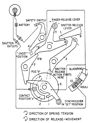
FIG, 6.11. A flash-lamp synchronization mechanism of the Acme Synchro shutter.
Figure 6.11 is a diagram of the basic design of the Ilex "Acme Synchro" shutter. If synchro-lever 1 has been set by being locked through latch-lever 7, release of trigger 5 will actuate latch-lever 7 and permit synchro-lever 1 with its contact to slide over contact 2, closing the flash-bulb circuit. After having traveled for a predetermined time, synchro-lever 1 hits lever 3 starting the shutter release 9. Stop 8 prevents trigger 5 from releasing the shutter if synchronizer is set. The duration of time-delay between closure of the electric circuit and start of the shutter opening can be adjusted by means of control disc 6 which carries contact 2. If adjustable contact is in position a, contact will be made shortly after synchro-lever has started its travel ; in other words, the longest available time-delay elapses from the time the electric circuit was closed until the time of shutter release. If contact 2 is shifted into the dotted position b, contact will be made shortly before shutter opening, the first part of the path being traveled through idly, resulting in shorter time-lag. Safety-switch 4 is controlled by the trigger as well as latch-lever 7 in their "unset" positions, as indicated in the diagram by 5' and 7'. This safety-switch keeps the electric circuit automatically interrupted just so long as the synchro-lever is not set for action and the trigger is not operated. This establishes a fully independent synchro-unit which is wound up and brought into coordination with the regular shutter mechanism by setting the synchro-lever.
To secure perfectly synchronized flash with X type High Speed lamps at full shutter opening, the lies shutter has a second contact 10. For (zero) or X setting, the control disc 6 is turned clockwise so far that it moves contact 2 entirely out of the reach of synchro-lever 1. Going through the same mechanical operation, synchro-lever 1 ,will release shutter over lever 3 without closing the electric circuit. The blades, moving into a predetermined position at full shutter opening, now close the firing circuit over the second contact 10. The setting of the synchro-lever provides in this case not only mechanical shutter release but permits also the safety-switch 4 to keep the electric circuit uninterrupted and ready for closure through the bladering contact.
The Kodak "Flash Supermatic 75 shutter with built-in flash synchronization also has a separate setting lever, whereas the Wollensak "Rapax" needs no extra cocking, but requires setting the time-delay indicator back to the "Off" position, in case a flash lamp should be in the battery case and no circuit closure for synchro-flash is desired. The flash contacts in the new Kodak "Synchro Rapid 800" shutter are automatic in operation and, therefore, no special cocking for flash is required.
Shutter Speeds and Exposure Time. The concept of shutter speed is not as simple as it seems and requires exact definition. Consider a complete shutter operation cycle as graphically represented in Fig. 6.12.
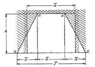
FIG. 6.12. Graph representing the opening of a lens shutter plotted against the time.
In this graph the opening of the shutter is plotted in relation to time. At start of the shutter operation, i.e., at the instant of shutter release (time t = 0) the shutter blades begin to open. Time T1 is required by the shutter to open fully aperture A (point a). The shutter blades stay wide open for a time, T2 (from a to b), after which the shutter begins to close again. After elapse of closing time T3 the entire cycle is completed, having consumed the "Total Open Time T". Assume that Total Open Time T is 1/100th of a second = 10/1000th of a second, or 10 milliseconds. Obviously, the actual amount of light admitted is not all the light which could pass were aperture A fully open during the entire cycle (Total Open Time), because a considerable part of it has been consumed by the opening and closing period, during which only a part of full aperture A admitted light. As can be seen from Fig. 6.12, the shutter was wide open only during time T2.
Efficiency of Between-the-Lens Shutters. The actual exposure time, therefore, will be the time which would permit an equivalent amount of light to pass through an ideal shutter, i.e., one in which the full aperture is open during the entire operation cycle. The area within the line o-a-b-c in Fig. 6.12 represents a measure of the actual amount of light admitted during the entire shutter-operating cycle. By geometrical relation this trapezoidal area is
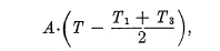
whereby
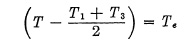
represents the effective exposure time.
The Total Open Time T would be equal to the actual or effective exposure time Te, if a shutter existed which could open and close so rapidly that the two periods T1 and T3 would become infinitely small.
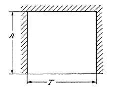
FIG. 6.13. Graph representing the operation cycle of an "ideal" shutter with an efficiency of 100%.
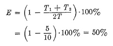
Figure 6.13 is an operating diagram of such an ideal shutter of 100% efficiency, but this, of course, is practically impossible; therefore, the efficiency of a shutter at full aperture is always below 100% and may be expressed mathematically by the ratio of the effective exposure time Te to the Total Open Time T Efficiency
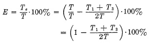
It can be seen from this formula that the efficiency E would become 100% if the subtracted part, consisting of T1 and T3, would become zero, i.e., if opening and closing time were to disappear. In a correctly designed shutter, the opening and closing times remain constant for any speed, since only time T2, during which the shutter blades stay wide open, is prolonged for longer exposures. It can further be seen that term (T1+T2)/2T will become smaller, as T, Total Open Time, becomes larger, since T appears in the denominator, while the numerator remains constant.
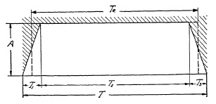
FIG. 6.14. Graph representing the operation cycle of an efficient lens shutter.
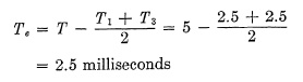
This may be proved graphically in Fig. 6.14, where the opening and closing times already appear to be relatively small as compared with Total Open Time T. In other words, efficiency quickly improves with longer exposure times, and, consequently, the effective or actual exposure time will not differ much from the Total Open Time T. An example with actual figures will make this clear. Assume that a shutter has a top speed of 5 milliseconds Total Open Time. The worst possible performance from any shutter of this type is that case wherein Total Open Time consists only of opening time T1 and closing time T3, and where no time is left for the wide open period T2. As a practical example, this case could occur with a double-ended blade shutter, where there is no reversal of blade movement; hence no stoppage of blades occurs when wide open. The operating diagram of such a shutter is shown in Fig. 6.15.
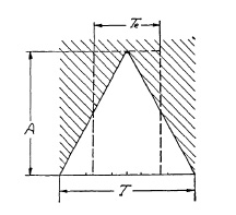
FIG. 6.15. Graph representing the operation cycle of a double-ended blade shutter.
The shutter opens in 2½ milliseconds and immediately starts to close, completing its closure in another 2½ milliseconds. The actual exposure time Te would be
Exposure to Stop Motion. Stopping motion with high-speed exposure deserves consideration because of popular misconceptions:
1. An absolute motion-stopping speed is nonexistent; although the outlines in the picture appear to be sharp and clearly defined, blur resulting from motion is merely not visible to the unaided eye.
2. With increasing enlargement this blur becomes increasingly visible ; therefore, the degree of final enlargement governs the amount of permissible blur.
3. The angle between the line of motion and the focal plane controls the depicted travel of a moving object and, therefore, determines the maximum shutter speed to be used.
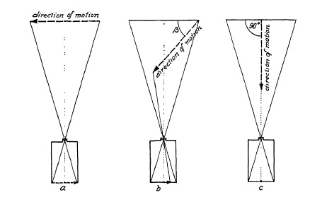
FIG. 6.20. Effect of direction of a moving object on the displacement of the image on the film.
The diagrams in Fig. 6.20 show how direction of motion influences the extent of blur. When the angle is zero, or the direction of motion is parallel to the film plane, the recorded travel of a moving object may have length a. When the angle (B in Fig. 6.20) lies between 0° and 90°, length b is recorded; whereas with the movement directly toward the camera (90° angle), only a point c is registered, which means that despite the object movement a considerably lower shutter speed is permissible.
The Light-Value Scale. In selecting the proper shutter setting two important factors must be considered. Obviously, for stopping fast motion, high shutter speeds are desirable. In many cases, however, the requirements of depth of field determine the diaphragm and this in turn the shutter speed.
In order to facilitate this task of adjusting speed and diaphragm opening under given light conditions, the relationship between diaphragm openings and shutter-speed settings has been made as simple as possible. The conventional diaphragm scale is marked so that each smaller opening requires double the exposure time of the preceding diaphragm. The shutter-speed scale in turn is arranged so that each slower speed represents approximately double the exposure time of the preceding. For example, if 1/200 of a second has been found correct for f/2, the next smaller diaphragm, f/2.8, would require twice the exposure time, or 1/100 of a second. Thus no complicated mathematical computations are necessary.
However, the latest development in shutter design has simplified this still more by making the relation between shutter speed and diaphragm opening automatic.
By making the spacings for the diaphragm openings and speed settings equal it is possible to engage mechanically the speed setting cam with the diaphragm setting lever. Once the proper correlation between f/stop and shutter speed has been determined by an exposure meter, the resulting "light value" can be kept unchanged by coupling speed cam and diaphragm lever. Any change in shutter speed will then automatically set the proper f/stop corresponding to that "light value."
In order to cover the range of possible light conditions, the light value 0 was assigned to an exposure time of 1 sec. at f/1. The following value 1 represents double the light value 0, hence requires ½ sec. at f/1, or 1 sec. at the next smaller aperture stop of f/1.4. Light value 2 is double the light value 1 or four times the value 0. Thus, a Light-value scale (LVS) of 1 to 20 covers all practical requirements, i.e., exposure times from 1/500 sec. to 1000 sec., and f/numbers from f/1 to f/45.
For more accurate correlation between f/stops and shutter speeds, the conventional speed scale 1, 2, 5, 10, 25, 50, 100, 250, 500 has been changed to 1, 2, 4, 8, 15, 30, 60, 125, 250, 500. This new scale makes the differencee in speed settings more nearly as the power of 2.
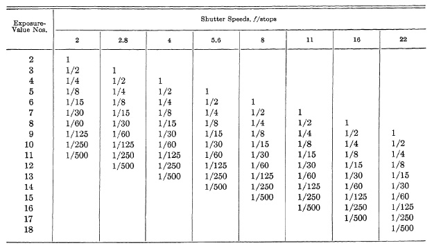
TABLE 6.2. SHUTTER SPEED AND LENS OPENING EQUIVALENTS OF EXPOSURE-VALUE NUMBERS
The LVS shutters prompted the market ing of exposure meters with LVS values, although those without LVS indications can easily be used (Table 6.2).
Stereo Shutters. For stereo photography perfectly matched lenses must be used, and exactly the same exposure time is necessary for the two stereo halves. To provide equal exposure time in stereo cameras a "master shutter" is coupled with a "slave shutter". The master shutter is equipped with a complete shutter mechanism; the slave shutter has only a diaphragm and shutter blades, both coupled to the master shutter and controlled by it.
Testing of Shutter Speeds. There are three methods of measuring shutter speed: (1) actual light admitted, (2) "Total Open Time", and (3) methods recording the complete cycle of shutter operation through its three periods.
Complete measurements of shutter speeds must show the three important periods of the entire shutter operation cycle, the opening, the wide open, and the closing, periods.
Because of their very nature, methods measuring actual amount of light admitted are the simplest. Many of them can be performed by any amateur of even little mechanical ability.
Measurement of Actual Exposure Time. A simple, and for all practical purposes sufficiently exact, method is the measurement of actual exposure time by the result as it appears on the exposed film. It is based on the assumption (not absolutely correct scientifically) that, for example, 200 exposures at 1/200th of a second and one single exposure at one second will produce the same negative density. The practical tester will, for example, compare 20 times 1/200th with 10 times 1/100th, or with 5 times 1/50th, or with 1/10th (or 5 times 1/25th with two times 1/10th, or with one 1/5th). If the recorded density on the film is uniform, then speeds may be assumed to be approximately correct.
Other simple methods for testing shutter speeds are based on making a photographic record of a body moving at a known velocity. To mention only a few of these, the full swing of a pendulum with predetermined period of oscillation, or the trace of any object falling freely under the acceleration of gravity. In this latter case the calculation is based on the well-known formula v=2gs, in which g is the acceleration of gravity (980.6 cm. per sec²) and s is the space through which the body has fallen up to the moment when the recording of its speed begins.
Another means of achieving a predetermined speed is that of using a white mark on the turntable of a phonograph, or a disc driven by a synchronous motor.
In all these methods the moving object will record a trace on the negative, the length of which will permit evaluation of the time the shutter was open. A convenient modification of these methods consists in photographing a neon lamp while moving the camera. In this case the camera need not be moved at any specific speed, since neon lamps glow alternately with the frequency of AC current. For example, on 60 cycle AC current, the neon lamp will glow 120 times per second and a series of bright dots similar to beads on a string will be recorded, each dot representing 1/120th of a second. Obviously, this latter method can be used only for testing speeds up to 1/100th of a second, or slower.
It should be remembered that all these methods record actual exposure time, since the opening and closing time of the shutter will be recorded only in part. The records all begin and end in a faded line, becoming brighter and stronger as the opening increases. Since the exact point where the visible trace begins to be recorded on the film cannot be accurately determined, these methods are sufficiently accurate for all practical purposes, but they do not render an exact picture of the en tire shutter operation cycle.
Measurement of Total Open Time and Efficiency. Measurement of Total Open Time and Efficiency is possible only with more complicated apparatus. Some of these methods are based on the principle of recording the opening and closing of the shutter on a moving film; others employ electronic methods of time measurement.
Electronic methods are being used to measure the amount of light admitted as well as the Total Open Time. In measuring the amount of light admitted, a photoelectric cell charges a condenser as soon as the shutter begins to open, and the charging stops at the instant closure is complete. The greater the amount of light passing through the shutter, the greater will be the electrical charge of the condenser. By discharging the condenser into a ballistic galvanometer the amount of the charge will be indicated. If correctly calibrated, the galvanometer reading will give a measurement of the amount of light actually admitted.
To measure Total Open Time, an electronic circuit is employed which measures the time interval from the very beginning of light admission to its very end, and not, as in the previous ease, the actual amount of admitted light. This "Total Open Time" remains the same regardless of diaphragm opening chosen, since the shutter opens from the center and closes toward the center.
A very exact method of recording the entire shutter operating cycle was developed by A. H. Katz, of the Aerial Photographic Laboratory at Wright Field, during the war.
Testing for Synchronization. The problem here is to measure the time-lag between the closing of the electric circuit and the instant the shutter is wide open. Again, testing principles may be classified into (1) those producing a photographic record and (2) those based on electronic devices. Electronic methods are faster and therefore more suitable for testing shutters in large numbers.
The simplest method, which may be applied by any amateur photographer, consists of photographing a flashing bulb. A piece of bromide paper (in place of the film) exposed at the top shutter speed with the synchronizer in action will show, after development, a picture of the flash bulb. If the flash bulb appears absolutely black, the shutter is well synchronized; but, if it is partly shaded or if the fine wires or foil shreds can be seen, synchronization is not accurate. If, with the same synchro-setting, another picture is taken at a slower speed, and a well-exposed picture of the lamp is obtained, it proves that the synchro-delay is too short, and this is now compensated for by the longer exposure. If no picture is obtained even then, time-lag is too long, i.e., the shutter does not begin its operating cycle until after the flash bulb has already reached its peak.
Various electronic devices have been designed which permit fast and reliable determination of the accuracy of synchronization. One of these methods involves a basic electronic circuit with a thyratron tube, a condenser, and a resistor. A condenser is charged from the instant the electric circuit of the synchronizer closes. At the start of the shutter opening, light passes through the opening blades, activating a photocell which in turn stops charging of the condenser. The amount of charge in the condenser is a measure of the time interval between circuit closing and shutter opening. This condenser charge is applied to a degenerative vacuum tube voltmeter which, calibrated in time units, directly indicates the elapsed time.
Technical Aspects of Higher Shutter Speeds. With the advent of faster emulsions and lenses of larger aperture, a demand for still higher shutter speeds has developed. Although ordinarily it is seldom that the top speed of present-day shutters is required, there does exist for certain purposes a definite need for still higher shutter speeds. Attempts to design between-the-lens shutters with higher speeds are being made constantly, but the problem is extremely difficult and no satisfactory solution is in sight at present. The problems involve mechanical considerations and, to a lesser degree, limitations in size and cost. For example, the parts of a shutter blade, pins, pivots, etc., must be as light as possible but sufficiently strong to withstand the strains set up in the rapid movements in opening, stoppage and closing, which involves a reversal of motion. Since the blades must be close together to be light-tight, friction is inevitable. Stronger springs would provide greater power for higher speeds but would increase strain and result in greater wear and tear of all parts. Heavier parts to withstand the added strain would require more space and increased driving power of the spring. Jewel bearings would lessen friction but cannot withstand the shocks and rough handling which many shutters receive. Lastly, all of these would require a larger and more costly shutter, and the trend in modern hand cameras is toward greater compactness, thus limiting the over-all size of the shutter.
All this should not be construed to mean that faster shutters cannot or will not be designed. Attempts to design shutters with higher speeds are continually being made. Besides the aforementioned method involving double-ended blades, some inventors have attempted to use two sets of blades timed so that one set is opening while the other is closing. This idea is not new and has been revived time and again. The principal objection to such a mechanism is that in the achievement of higher speeds the blades of the open set will have to start closing even before the closed set has completed its opening. Consequently, they will meet somewhere in a half-open and half-closed position, reducing maximum aperture just when it is most needed. Despite this, shutters with a top speed of 1/1000 second have been developed with apertures up to 1 inch.
Focal-Plane Shutters. The focal-plane shutter has provided one answer to the need for extremely high shutter speeds up to 1/1000th of a second and higher.
Focal-plane shutters operate according to an entirely different mechanical principle. Instead of moving blades between the lens elements, a curtain is positioned near the focal plane. The curtain is opaque and highly flexible and is tensioned between two rollers. A slit in the curtain across the line of movement admits light to the film, and various adjustable spring tensions pull the curtain across the focal plane at different speeds. Slits of different width in combination with different spring tensions result in a great variety of speeds.
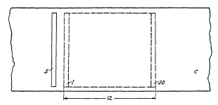
FIG. 6.21. Exposure with the focal- plane shutter.
Total Exposure Time vs. Local Exposure Time. Distortion. Figure 6.21 indicates the outlines of the picture size a, the curtain c with slit s. When curtain c moves across frame a, slit s admits light to the film. Unlike the between-the-lens shutter, such an exposure will not be completed at the same instant, but rather strip by strip. Assume that slit s equals 1/20 of frame size a, then exposure of the entire frame is actually accomplished in consecutive strips of width s. The fact that there is no reversal from an opening to a closing movement, as in a between-the-lens shutter, but only one continuous motion also accounts for faster speed. It should be observed that "Total Exposure Time" is the time from exposure of the first strip of the film to the moment when the last strip has been exposed, while "Local Exposure Time" is the period in which each point on the film is actually exposed. If, for example, 1/1000th of a second (one millisecond) exposure time is required, and the curtain has been adjusted so that it moves at such a speed that the width of slit s is traversed in that exact time, then the last strip "20" in Fig. 6.21 will be traversed 20/1000 (20 milliseconds) after the first width "1" has been exposed. Obviously, a fast moving object photographed at 1/1000th of a second may well be "stopped" in motion and a satisfactorily sharp picture, strip by strip, may result. However, after 20 milliseconds, when the last strip is being exposed, the position of the fast moving object might well have changed in the interim, inevitably resulting in a distortion of the pictured object. The extent of this distortion will depend largely on the relationship between the direction of the moving object and the direction of the moving curtain slit.
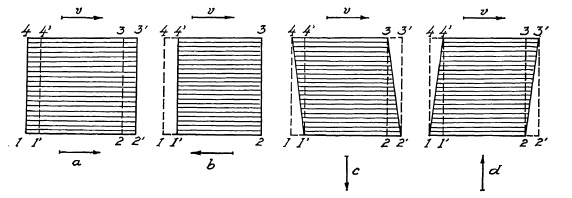
FIG. 6.22. Distortion with the focal-plane shutter.
A square-shaped object, moving left to right in the focal plane at a certain speed v in Fig. 6.22, moves from its original position (1, 2, 3, 4) to its new position (1', 2', 3', 4'). If the curtain travels in the same direction a in Fig. 6.22, and requires the same time for the complete cycle of exposure from the very first strip to the last, this last strip of film will be exposed when the image of the square in the film plane has already moved to the new position (1', 2', 3', 4'). Consequently, the image of the square will assume rectangular shape (1, 2', 3', 4) in Fig. 6.22a, i.e., it will appear longer (distorted). Should the slit move in a direction opposite to that of the pic tured object motion, as indicated by arrow b, then the image of the square will become rectangular with shortened horizontal sides (1', 2, 3, 4') in Fig. 6.22b. If the curtain moves in the direction of arrow c, then the last strip at the bottom will be exposed when the edges (1, 2) will have moved to a new position (1', 2'), and the resulting image of the square will be distorted into a parallelogram (1', 2', 3, 4) in Fig. 6.22c. With the curtain moving in direction d, the last strip will image line (3, 4) in the new position (3', 4') to which it has proceeded in the meantime, resulting in a parallelogram (1, 2, 3', 4') as shown in Fig. 6.22d.
In general, these distortions are not objectionable, since in most cases they will be scarcely noticeable. In some photographic applications, however, distortion is highly objectionable, e.g., in aerial photography for mapping, precluding the use of the focal-plane shutter.
Factors Affecting Exposure with a Focal-Plane Shutter. In discussing the factors involved in the timing of the focal-plane shutter, its position at a distance in front of the focal plane must be considered (see Fig. 6.23).
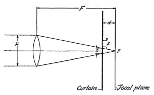
FIG. 6.23. Effect of distance between curtain and focal plane on exposure with a focal-plane shutter.
In some cameras this distance d is appreciably large. Figure 6.23 shows how the slit of the curtain with its width s approaches the light cone coming from an infinitely distant point after passing through lens of aperture A, imaging point P in the focal plane. At distance d, the light cone admitted through slit s has not yet entirely converged to point P and therefore still has a considerable diameter o. The six distinctly different exposure phases of point P are indicated in Fig. 6.24.
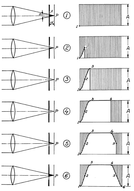
FIG. 6.24. The six exposure phases with a focal-plane shutter.
In phase 1 the light cone is still prevented from reaching the film. The exposure curve in the diagram to the right is about to start at point 1. In phase 2 half the cone o passes through, half of it still being prevented from reaching the film, and the shutter-operation curve has moved to point 2. In phase 3 the slit fully admits light cone diameter o; the full lens aperture is utilized and curve moves to point 3. In phase 4 slit s moves further on where its other edge is about to enter into the cone. During this period the full lens aperture is still utilized and the curve continues to point 4. In phase 5 the upper half of the light cone is cut off by the upper (closing) edge of slit s. Only half of light cone o is admitted. The shutter-operation curve has started its downward trend and moves to point 5. In the last phase (6), cone o has been cut off entirely, all light admission is ended and exposure of the film strip is complete. Curve ends at point 6.
Testing of Focal-Plane Shutters. Some of the methods used for testing between-the-lens shutters can also be used for focal-plane shutters. Other devices, especially designed for focal-plane shutters, have been developed.
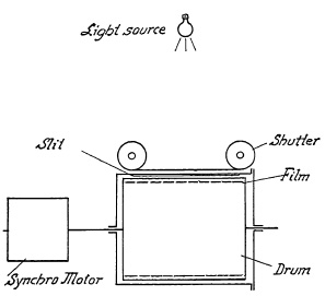
FIG. 6.26. Diagram of a shutter speed tester.
Among the test devices, applicable to both between-the-lens shutters and focal-plane shutters, is one which consists of a transparent drum enclosed in a lighttight housing (Fig. 6.26). A synchronous motor drives the drum at speeds variable from 60 to 4000 r.p.m. A film strip is inserted around the drum's cylindrical circumference by opening the housing at one end. Atop the housing a slit equal to the width of the drum is provided parallel to the drum axis. The shutter under test is placed over the slit so that the curtain travel is parallel to the drum axis. A light source placed above the shutter at a suitable distance will photographically record a strip as shown in Fig. 6.27.
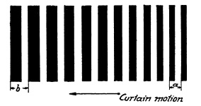
FIG. 6.27. Exposure time record made by shutter speed tested in Fig. 6.26.
This photographic record provides all data necessary to determine the shutter speed. AC is a measure of the effective exposure time at this point in the focal plane. AB is the chosen width of the curtain slit. The movement of the film is controlled by the chosen speed of the rotating drum V in inches per second; then the effective exposure time is T=AC/V. With the f/stop chosen and the distance of the curtain from the focal plane known, efficiency may be computed as previously explained: E=s/(s+d/f).
Another method makes use of the Strobotac, an electric stroboscope producing from 10 to 240 flashes per second. Directed toward a strip of film which is exposed through a focal-plane shutter, a photographic record of all flashes occurring throughout the entire shutter operating cycle will appear similar to that in Fig. 6.28.
FIG. 6.28. Exposure time record made by the Strobotac.
The space, traveled from one strip to the next, a, b, will be a measure of the actual curtain speed. If, for example, the Strobotac were set for 200 flashes, each distance from one strip to the next corresponds to the time interval of 1/200th of a second. The fact that distance a is shorter than distance b at the end of the total exposure indicates that the curtain speed does not remain constant during the entire operating cycle, a condition found in practically every type of focal-plane shutter, which is caused by the greater initial friction of the start of its movement, and because the mechanism needs time for acceleration. This definite disadvantage of the focal-plane shutter may also be observed in Fig. 6.27, where distance a is greater than b.
Synchronization of Focal-Plane Shutters. Synchronization of the focal-plane shutters involves problems quite different from the between-the-lens shutter because of the difference in the characteristics of the two shutters. A distinction must be made between local exposure time (exposure time of one point of film) and total operation time (time required to expose the entire film), and it must be realized that a shutter with a slit of perhaps 1/8" and a speed of 1/1000th of a second has to travel 1/8" in that 1/1000th of a second without considering efficiency. If the film size is 4"x5" and the curtain is to travel across the width of the film, i.e., 4", there are 32/8" to be traversed, which will consume 32/1000th of a second until the exposure of the entire film is complete. Hence, flash bulbs, made especially for use with focal-plane shutters, have a longer peak to allow for this long exposure time.
The difference in the speed of the curtain at the beginning and the end of exposure may also cause different densities in different parts of the negative. In view of the fact that only small strips of film are exposed at a time, not all the light of the flash can be utilized and, consequently, efficiency is lower. Under identical conditions, the low peak of the focal-plane lamp requires larger lens apertures than the high peak lamp used with between-the-lens shutters.
Synchronization of the focal-plane shutter does not present any serious mechanical problems. On almost every focal-plane shutter a part can be found which is accessible from the outside (knob, for example) which moves as the focal-plane shutter operates, and a contact can easily be adjusted to be activated by this part. Some cameras have built-in synchronization with an outlet socket in the back of the camera.
Comparison of Between-the-Lens and Focal-Plane Shutters. In comparing focal-plane and lens shutters it must be realized that one type performs tasks which cannot be fulfilled by the other.
Advantages of the between-the-lens shutter are:
1. Simple handling.
2. Relatively small size, providing convenience in small folding cameras.
3. Freedom from distortion on moving objects because of simultaneous exposure of the entire picture.
4. Even density over the entire negative because of simultaneous exposure.
5. Correct synchronization is more readily achievable with short and high-peak flash lamps.
Advantages of the focal-plane shutters are:
1. Higher speeds to "stop" fast motion.
2. Ready interchangeability of lenses because of separate shutter and lens mount.
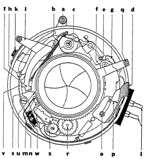
FIG. 6.29. Mechanical elements of the supermatic shutter.
Some Representative Lens Shutters. The mechanism of a typical precision lens shutter (Kodak Supermatic) is shown in Fig. 6.29. Setting lever a sets up tension in spring b; at 1/400 sec. an additional spring located under eccentric member c is brought into action. Shutter speeds are changed by turning speed-selecting ring d which, by means of cams shown as dashed line, actuates controls. The step-shaped cam at e controls the extent of engagement of gear sector f with one member of gear train retarding mechanism g, and a cam, not shown, controls position of an oscillating pallet relative to a ratchet (star) wheel. T and B are determined by positions of levers h, also controlled by a cam. The release lever is marked i; and the socket for the cable release is k.
Flash discharges with no time-lag are synchronized with shutter-blade action by an electric circuit formed through prongs l, closing it at m through post n which moves upward when blades open.
Photoflash lamps of 5 milliseconds time-lag are synchronized by setting F on the limiting stop o opposite index p. Clockwise movement of lever q sets up spring tension through gear train r and moves cam s upward. Downward pressure on lever i now allows its extension t to move sideways to cam u. Lever v follows and opposite end closes contacts w. This releases gear train which, through downward movement of step between cams s and u, actuates lever t and releases shutter so blades are fully opened about 5 milliseconds after electric circuit has been closed.
Synchronizing flash lamps of 20 milliseconds time-lag is accomplished similarly. Limiting stop o at M permits movement of lever q which, in addition to the action described above, engages oscillating pallet x. The pallet action slows down counter-clockwise travel of "step," and shutter is released so that "fully open" is reached about 20 milliseconds after contacts w have closed.
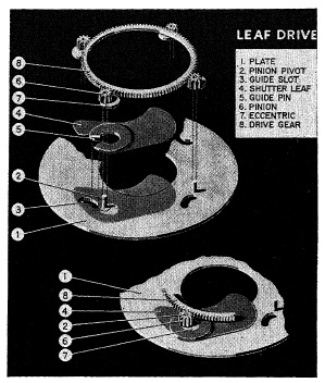
FIG. 6.30. The Graflex 1000 shutter.
With but few exceptions, the maximum shutter speed of between-the-lens shutters is 1/500 sec. One of these exceptions, the Graflex 1000 shutter, is shown in Fig. 6.30, which is an exploded view of the shutter- blade movement. Four pinions (6) are driven by a single ring gear. Attached to each pinion is an eccentric (7) which rotates within a bearing attached to the shutter blade (4), of which only one is shown for clarity. Attached to the leaf-bearing is a guide pin (5) which is forced to move in a curved guide slot (3). The movement of the shutter blade (4) is now controlled by the action of the eccentric (7) and the guide pin (5) in the curved guide slot (3). This combined movement causes the blade to follow an elliptical path.
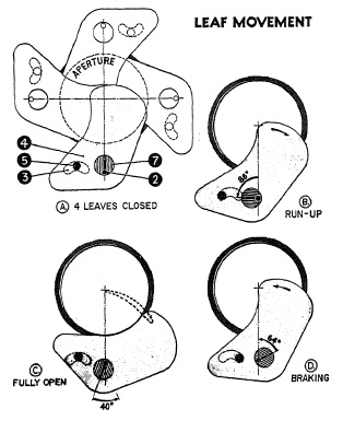
FIG. 6.31. Leaf movement in the Graflex 1000 shutter.
In Fig. 6.31(A) the shutter blade is shown in the fully closed position. Note that the blades overlap each other considerably. This allows the blades to start moving relatively long before the shutter is opened. This starting or "run-up" phase (B) of the blade movement accounts for about 86° rotation of the eccentric (7), after which leaf (4) is just beginning to open. As the eccentric continues to rotate counterclockwise about the pinion pivot (2) the blades have already obtained considerable speed at the moment they start to open. This helps to shorten the opening time. In (C) the blade is fully clear of the aperture. The eccentric continues to rotate about 40° during which phase the blade slows down and starts speeding up again for the return stroke.
This is the " dwell' '-period which is controlled by the retarding mechanism to produce slower shutter speeds. The ellipse-like movement is shown in dotted line in (C). In (D) the aperture is completely closed again, but the eccentric continues to rotate for about 64° before the blades come to rest. During these 64° the blades are slowed down to a gentle stop.
It can easily be seen that the shutter aperture is open fully for only 40° of the 360° rotation of the eccentric, or 1/9 of the total operational movement. Thus, nearly half of the total movement is used for accelerating and slowing down the shutter blades without opening the shutter aperture, namely 86° in the "run-up" phase and 64° in the slowing down period.
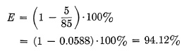
The efficiency of the Graflex 1000 shutter can be calculated as follows : The Total Open Time T is 360° - 150° = 210°. Since the dwelling phase is 40, the Opening Time T1 and Closing Time T3 are together 210° - 40° = 170°. Thus the efficiency of this shutter at top speed is:

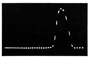
FIG. 6.32. Oscillograph trace of the Graflex 1000 shutter at 1/1000 sec. setting.
An oscilloscope recording made by Graflex is shown in Fig. 6.32. Produced by a crystal-controlled oscillator, each five dots equal 1/1000 of a second. The oscillogram shows how close the Graflex 1000 shutter approaches the goal of 1/1000 of a second.
In order to withstand the stress on the shutter blades caused by such high speed, the blades are made of magnesium instead of steel. The reduced weight and lower inertia makes it possible to utilize more of the available spring power for faster acceleration. The large overlapping area and the braking phase, before the blades come to a full stop at the end of their operating cycle, helps prevent the blades from crossing, a difficulty encountered with all shutters at high speed.
Representative Focal-Plane Shutters. Focal-plane shutters may be divided into two types: one consisting of a single curtain with a number of apertures of different widths; the other of two curtains, the width of the aperture being varied by the positioning of the two curtains.
The Graflex focal-plane shutter (Fig. 6.33) is typical of single-curtain shutters. The black curtain is mounted on two rollers and is located directly in front of the film. It is moved by spring action, and .the curtain openings (slits of selected width) allow the light to reach the film. The bottom roller is a hollow shaft. A spring A is attached to the inner stationary shaft with one end, and to the hollow shaft with its 'Other end. When the curtain is pulled up, the bottom roller is rotated counterclockwise as viewed in the insert of Fig. 6.33 against the tension of spring A. The curtain is rolled up by rotating the winding key clockwise. Rotation of the winding key is transmitted to the top roller through the master gear and the top roller pinion. The latter meshes with the shutter dial which is geared and indicates the speeds to which the shutter has been set. To prevent the winding key from rotating counterclock wise, the master gear is equipped with two arms (A and B in Fig. 6.34a), placed 180° apart, either of which will hit against surface C of the escapement cam in Fig. 6.34a. Clockwise rotation of the winding key is possible because the escapement cam is held in a down position by the escapement spring, but arm A or B will pull up the cam by pushing against surface E.
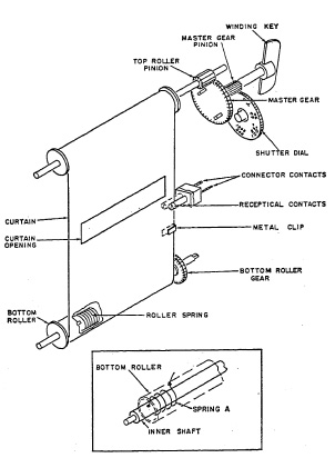
FIG. 6.33. The single-curtain Graflex focal-plane shutter.
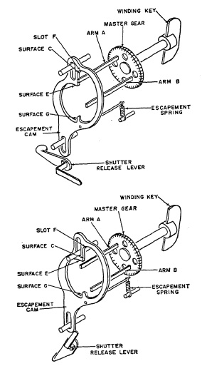
FIG. 6.34. Detail of Graflex focal-plane shutter mechanism.
Once past this surface, arm A or B goes into slot F; then the escapement cam is pulled down by the escapement spring thus preventing counterclockwise movement of the master gear. The tension of spring A (Fig. 6.33) in the bottom roller is transmitted to the master gear by the curtain, top roller and top roller pinion. Therefore, the curtain is kept in the selected position, as indicated by the speed indicator, as arm A or B of the master gear locks against surface C of the cam (Figure 6.34b). The shutter is now set, the curtain opening corresponding to the selected speed is just above the film, and the shutter is ready for exposure.
Operating the shutter release lever pushes the escapement cam up against the tension of the escapement spring. Arm A of the master gear is now free to rotate counterclockwise, pulled by the tensioned bottom roller spring. After half a revolution of the master gear, arm A is stopped by surface G of the escapement cam. The gear ratio is such that the half revolution of the master gear enables the curtain opening to move across the film from the top to the bottom roller. Releasing the shutter release lever allows the escapement cam to be moved to its down position, freeing arm A of surface G, but preventing further counterclockwise rotation by arm B which now hits surface C of the escapement cam.
Three speeds of the shutter, namely 1/1000, 1/250, and 1/50 of a second are controlled only by the tension of spring A in the bottom roller. The length of the exposure depends on the spring tension and on the width of the selected curtain opening. The small curtain opening is about 1/8 in., the medium size opening is about 3/8 in. wide, and the large opening is about 1½ wide. A governor, consisting of gears which can be caused to mesh with the bottom roller gear, drives brake shoes against a fixed ring by centrifugal forces, providing braking action which decreases the speed of the bottom roller. This action retards the travel speed of the curtain. The three speeds mentioned (1/1000, 1/250, and 1/50) are thus reduced to 1/500, 1/250, and 1/30 sec. The curtain opening for time exposure is about 6 in. wide.
In Fig. 6.33 metal clips are shown which are located on one edge of the curtain at a certain distance from the curtain opening. These metal clips establish electrical contact between the receptacle contacts when the curtain moves downward, and the flash lamp is fired. For open flash pictures a similar clip on the edge of the curtain is located along the center line of the "Time" opening (6 in. wide). When the shutter is set to T electrical contact is established between the receptacle contacts by the metal clip at the instant the full shutter opening is reached. By operating the release lever a second time the curtain rolls to cover the film and close the shutter.
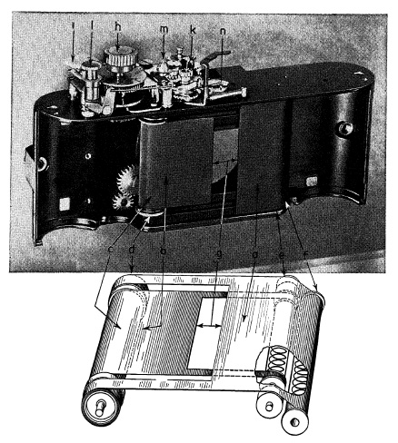
FIG. 6.35. Focal-plane shutter of two curtains on a miniature camera.
A drawing and photograph of a focal-plane shutter mechanism on a miniature camera are shown in Fig. 6.35. Operating the lever on the back of camera first brings edge of curtain a over edge of curtain b, and then winds them together across film aperture onto rollers c and d, setting up spring tension in rollers e and f. Shutter speeds of 1/50 to 1/1000 sec. are determined by width of the curtain opening g, regulated by knob h which turns roller c in relation to roller d. Acceleration is compensated for by widening of slit as it travels across film plane due to difference in diameter of rollers c and d. Speeds 1 to 1/25 sec. are selected with dial i and controlled by an escapement mechanism k which varies the delay of curtain b after curtain a has completed its run. At B setting, curtain a moves across when the release button l is pressed down and curtain b follows when button is released.
In most 35 mm. cameras the interval between the leading and trailing curtains forming the shutter aperture uncover the entire image at speeds below 1/30-1/60 sec., depending on the shutter. Under these conditions electronic flash lamps may be used or flash lamps designed for use with between-the-lens shutters. Many 35 mm. cameras with focal-plane shutters have X synchronization for electronic flash up to a speed of about 1/50 sec. and in synchronization for flash lamps over the same range of exposure times. Electronic flash cannot be used at higher speeds because the opening in the curtain exposes only a portion of the image during the duration of the flash. FP (focal plane) flash bulbs must be used at shutter speeds faster than about 1/50 sec.
Focal Encyclopedia of Photography, The Macmillan Co., New York, 1959.
FREYTAG, The Contax Way, Focal Press, London and New York.
HAYES, Iris Shutter Analysis, Amer. Phot., p.34 (November 1942).
LIPINSKI, Precision Cameras, Focal Press, London and New York.
PBITSCHOW, Die Photographische Kamera und ihr Zubehor, Vol. 2, Handbuch der Wissenschaftlichen und Angewandten Photographie, Springer, Vienna, 1931.
1 All statements to the effect that shutter efficiency may run lower than 50% are therefore wrong.